Question
How long is your longest Liquid Leakage Sensing Band? Also, how do you join two Bands together?
Answer
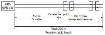
1. The maximum length is 100 m.
The possible lengths of sensor cable for a Water Leak Detector (61F-GPN-V50, 61F-WLA) for different lengths of Sensing Bands (F03-15, -16PE, -16PT) are shown below, where the reset current is set at a minimum of 0.15 mA. When the leakage current of the sensing band set to more than 0.15 mA, the water leak detector cannot reset. When the leakage current of the Sensing Band is less than 0.15 mA, the corresponding cable length is okay.
Possible Length of Sensor Cable (Sensing Band + IV Cable)
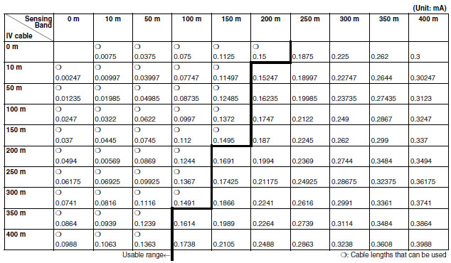
Note:IV cable (2 mm2), Sensing Band (F03-15, F03-16PE)
2. The sensing bands can be joined together with the following steps.
Connecting Water Leak Detector Sensing Bands
F03-15 Sensing Band
(1)Connecting the Sensing Band Directly to the Water Leak Detector
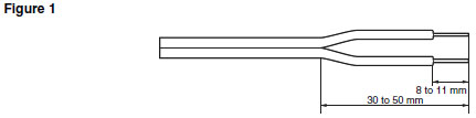
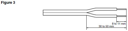
Strip away about 8 to 10 mm of the sheath from the end of the sensing band.
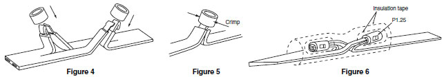
(2)Connecting the Sensing Bands Together
Connect the sensing bands using an insulated crimp sleeve or a closed end connector. Install a pull box (e.g., plastic) and keep the connected section inside it to keep it well insulated. If a pulling box cannot be installed, wrap some insulation tape around the connected section to keep it well insulated. When using a closed end connector, select cables that are similar in size and stiffness to the sensing cable. If a dissimilar cable must be connected, twist the more flexible cable around the stiff cable and use the closed end connector as a standoff connector. If required, remove any electrodes that are attached in close proximity to the connected section.
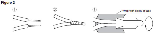
After putting the closed end connector over the joined section, pull the cable and wrap insulation tape around it.
Note:Use AMP Closed end connector, product number 35653 or equivalent.
F03-16PE Sensing Band
A standard F03-16PE sensing band is made from 0.3 x 1.5 rectangular lines.
(1)Connecting the Sensing Band Directly to the Water Leak Detector
Strip away about 8 to 10 mm of the sheath from the end of the sensing band and then connect it.
(2)Connecting the Sensing Bands Together (Using Crimp Sleeve P-1.25 or B-1.25)
Note:P-1.25 and B-1.25 are JIS titles for general electrical wiring.
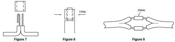
(a)Cut a slit in the center of the sensing band with a utility knife. Leave the insulation intact on the inside.
(b)Strip back the insulation so that the enough wire is exposed to fit into the sleeve in the configuration shown in Figure 7.
(c)Pull the sleeve over the wires and crimp in the directions shown in Figure 5 and Figure 8. Pull on the wire to check whether the crimping is effective.
(d)Wrap each connection with insulation tape, then bend the connected sections in opposite directions as shown in Figure 6. Wrap the whole section with insulation tape for protection (see Figure 6).
(3)The sensing bands can also be connected by inserting them from opposite ends of sleeve.
As shown in Figure 9, the sensing bands can be inserted from opposite ends of the crimp sleeve to meet in the middle. Either P-1.25 or B-1.25 crimp sleeves can be used but make sure that the crimped section is big enough to fit three folds of the cable conductors.
Crimp in the directions as shown in Figure 5 and Figure 8.
Wrap each connection with insulation tape, then wrap the whole section with insulation tape again for protection.
(4)Connecting the Sensing Band and Lead Wires
Connect the sensing band and lead wires using the method described in the previous item (3). Use a B-1.25 crimp sleeve. (Refer to Figure 9.)
Recommended Products


Other Level Switches FAQ
-
 Why do the specifications for the High-sensitivity 61F Floatless Level Controller say, "possible to use with 15 kOHM or less, however, this may cause reset failure"?
-
Can two 61F Floatless Level Controllers and two Electrode Holders be used in the same tank?
-
When voltage is applied to 61F Floatless Level Controller, it operates regardless of the actual liquid level. What is the cause of the problem and how can it be corrected?