Wiring Systems
|
|
Features |
| Principles | Classifications |
| Engineering Data |
|
| Explanation of Terms | Troubleshooting |
-
 Names
Names
-
 Configurations and Structures
-
 Electrical Performance
-
 Mechanical Performance
-
 Information on Standards
Names
Contacts and Housing (Mold)
Contact: A metallic part or contact terminal for making an electrical connection
Housing (mold): An insulator that houses contacts in an appropriate array, and isolates a contact from other contacts or conductors.
Plugs and Sockets
Connectors are classified as plugs or sockets according to the shape of the contact section or according to the connector that has the contacts.
Plug: Same as male connector, pin header, or post.
A connector with fixed contacts.
Mates with the socket contacts to make electrical connections.
Socket: Same as female connector or receptacle.
A connector with moving contacts.
Mates with the plug contacts to make electrical connections.
Harness
A part with wires attached to connectors.
Minimum Packing Unit
The minimum number packed for shipment from the factory.
Number of Pins
The number of contacts.
A synonym for pin count.
Pitch (Between Rows)
The interval between terminals in the long direction (distance between the terminal centers).
There is also a pitch between rows, which indicates the interval (distance between terminal centers) between rows of terminals in the long direction.
Through Holes
Holes into which terminals are inserted in order to connect connector terminals to the PCB wiring pattern.
Connector terminals are inserted into these holes and soldered to make the electrical connections.
A through hole sometimes indicates a hole used to connect the front and rear side wiring patterns of a PCB.
AWG
AWG is an abbreviation for American Wire Gauge. It is a conductor standard that indicates the core cross-sectional area for wires generally used in the United States.
Plating
Surface treatment that covers the surface of a metal or other material with a thin metal film (examples: gold plating or tin plating).
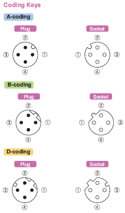
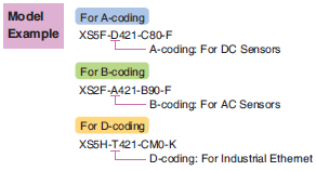
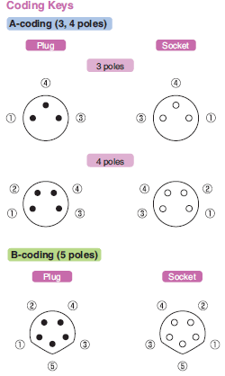
Coding
Processing performed on the housing in order to prevent incorrect insertion during connector mating.
Solid Wire and Stranded Wire
Both solid wire and stranded wire are conductor structures of cables. A solid wire is made of a single conductor, and therefore, the cable is somewhat rigid and is used for longdistance transmission. A stranded wire is made by grouping together several thin conductors, which makes the cable flexible so that it can be easily routed. However, it is unstable for long-distance transmission. At OMRON, we mainly use stranded cables.
Cat (Category)
A standard for Ethernet Cables and Connectors that indicates the transmission characteristics (communication speed). As the category number increases, it becomes easier to support high-speed communication. Choose and use Cables with Connectors of the recommended category or higher for the connecting devices.
STP and FTP
A cable in which two wires are twisted in a pair is called a twisted pair cable. Such a cable is less susceptible to noise and is therefore most popularly used as a communication cable including an Ethernet cable. When used in production equipment at a factory (FA), it is further shielded to improve noise resistance, and is called as STP (Shielded Twisted Pair) or FTP (Foiled Twisted Pair).
UTP
UTP (Unshielded Twisted Pair) is an unshielded (without shield) twisted pair cable. It is different from a shielded STP or FTP.
Single-Shield and Double-Shield Cables
Generally, shielded STPs or FTPs are used as Ethernet cables in production equipment at factories (FA). Single and double indicate the number of shields. The shield construction is expressed as overall/individual shield TP (twisted pair) such as F/UTP in the case of single shield and S/FTP in the case of double shield.
Straight and cross Cable (Connection)
A cable in which the wires do not cross each other (same pin array on both sides of the cable) is called a straight cable, and a cable in which the wires cross midway (different pin arrays on both sides of the cable) is called a crossover cable. At OMRON, we mainly use straight cables (connection).
PoE
PoE (Power over Ethernet) enables the supply of power to PoE-compatible devices using Ethernet cables of category 5 or higher and is standardized by IEEE802.3at. It saves wiring as an AC adapter is no longer required.
Configurations and Structures
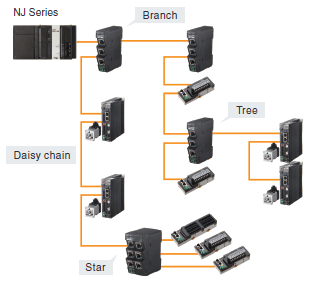
Bus Line Connection
A form of connection in which multiple devices are connected one at a time to a single main line. As compared with other forms of connection, a shorter cable is required and a relay device such as a hub is not needed, which has the advantage of a lower construction cost.
Daisy Chain
It is a technique of connecting peripherals or other devices with cables in which the devices are tied in a row. Wiring can be efficiently performed, and even if a cable fault occurs, it can be quickly replaced.
Tree Connection
A form of connection in which wiring and peripherals are connected on branches from one root node. Since the peripherals (nodes) are not mutually affected, this form of connection is strong against device failure.
Star Connection
A form of connection in which multiple peripherals (nodes) are wired in the shape of a spoke wheel through a switching hub.
The degree of freedom of wiring is high and the cables connected to the switching hub are independent, because of which this form of connection has the advantage of being strong against device failure.
Electrical Performance
Rated Current
A current that serves as a reference for connector use.
The rated current is normally specified according to the temperature rise limit of the connector contact section, connection section, etc.
Rated Voltage
A voltage that serves as a reference for connector use
Contact Resistance
The electrical resistance between contacts when the connectors are mated in the normal usage state.
This electrical resistance is found by supplying the specified test current and measuring the voltage at the specified contact location. Therefore, this always includes the resistance of the contact conductors. Normally, a low-level contact resistance (measurement current: 100 mA max., open voltage: 20 mV max.) is given.
Insulation Resistance
The value of the resistance to the leakage current that flows through the insulator when the specified voltage is applied between adjacent contacts on the connector or between a contact and other adjacent metal.
Dielectric Strength
The limit to the voltage between adjacent contacts on the connector or between a contact and other adjacent metal for which no insulation breakdown, flashover, or other abnormality occurs within a certain time (normally, 1 minute).
Mechanical Performance
Insertion Tolerance
The minimum number of repeated connection (insertion) and disconnection (removal) operations that a connector can withstand.
The number of operations for which the base metal is first exposed is used as a guideline.
Note:This is not the number of operations that indicates the contact resistance rise limit.
Ambient Operating Temperature Range
The ambient temperature range around the connector in which it can be used in normal condition.
(There must be no condensation at low temperatures.)
Vibration
The range of mechanical vibration in which the connector satisfies its performance and characteristics requirements.
Information on Standards
IEC Standards: Specifications and Mating Dimensions
The specifications and mating dimensions of M12 Connectors comply with IEC 61076-2-101.
Model Example
The specifications and mating dimensions of M8 Connectors comply with IEC 61076-2-104.
Model Example
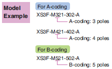
Note:
1. Note that even if the coding is the same, the rated voltage and current value vary depending on the number of poles.
2. The pin arrangement is common for M12 connectors with 3, 4, and 5 poles.
Therefore, if coding is the same and “Number of poles of the plug < or = Number of poles of the socket”, a connection
can be achieved even with different number of poles (Example: An A-coded 4-pole plug can be connected to an
A-coded 5-pole socket.).
In the case of an M8 connector, a connection cannot be completed if the number of poles is different.
Therefore always use a combination of a plug and socket having the same coding and number of poles.
3. In addition to the above, M12 connectors are available in 5-pole and 8-pole types. For details, see DeviceNet Catalog
(Cat. NO. Q102-E1).