Power Controllers
OMRON provides single-phase/three-phase Power Controllers with a phase control system and Multi-channel Power Controller that enable high-precision temperature control with optimum cycle control.
|
|
Features |
| Principles | Classifications |
| Engineering Data | Further Information |
|
|
Troubleshooting |
-
 Fuse Connections (Constant-current Models)
-
Output Modes for G3PW Phase Control
-
G3PW Wiring Methods
-
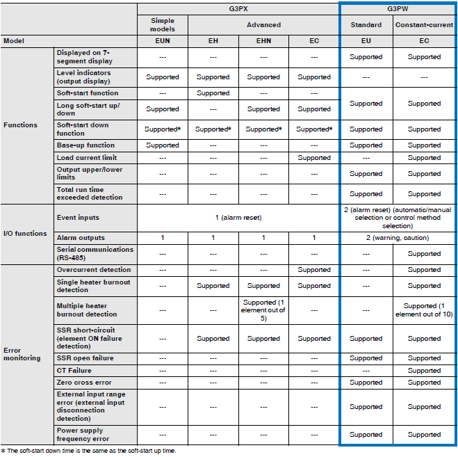
Comparison with Discontinued Products
-
Connection Examples of G3PW and Temperature Controller
Fuse Connections (Constant-current Models)
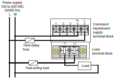
When using the Constant-current Model, the G3PW Power Controller cannot be protected against load short circuit.
If short-circuit current flows, the elements will be destroyed before the constant-current or overcurrent detection currents operate.
To protect the G3PW from short-circuit accidents, connect a quick-burning fuse.
Quick-burning Fuses
| Product model | Fuse model | Fuse Holder |
| G3PW-A220E[]-[][][] | CR6L-20/UL | CMS-4 |
| G3PW-A245E[]-[][][] | CR6L-50/UL | |
| G3PW-A260E[]-[][][] | CR6L-75/UL | CMS-5 |
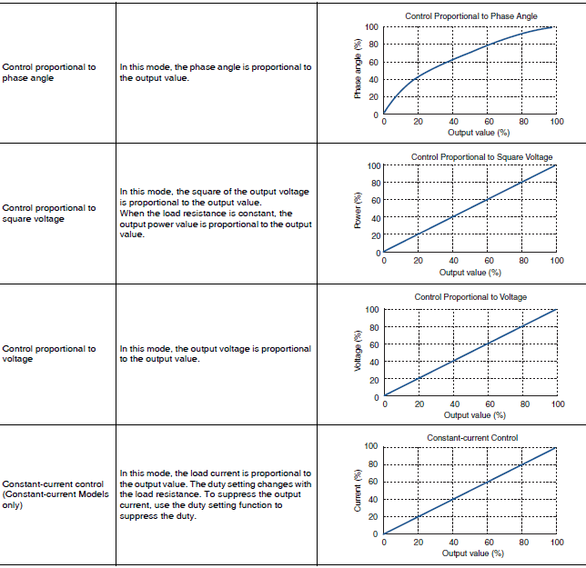
Output Modes for G3PW Phase Control
For the G3PW, when phase control is used as the control method, you can select from the following four modes for the relationship of the control value to the output value.
G3PW Wiring Methods
Wiring the Power Supply and Load Circuits
First, connect the load to load terminal T1 and to the power supply, and then connect the power supply to load terminal L1 through a fast-acting fuse.
Connect the AC power supply to power supply terminals 4 (N) and 5 (L).
The AC power supply ground polarity and the G3PW terminal block polarity are not related, but connect the 4 (N) and 5 (L) terminals on the command input/power supply terminal block and the T1 and L1 terminals of the load terminal block to power supplies with the same phases.
Always connect the load to load terminal T1.
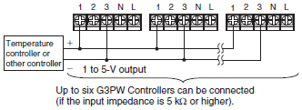
Command Input and Power Supply Terminal Wiring Voltage Input (1 to 5 VDC)
When using a voltage input, connect the positive and negative signal wires to terminals 1 and 3, respectively.
Example:
For a linear voltage output, if the input impedance is 5 kΩ or higher, up to six G3PW Controllers can be connected.
Current Input (4 to 20 mA DC)
When using current input, connect the positive and negative signal wires to terminals 2 and 3, respectively.
Example:
If a temperature controller with a current output has an input impedance of 600 Ω or higher, up to six G3PW Controllers can be connected.

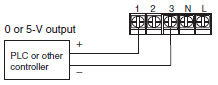
ON/OFF Voltage Input (0 or 5 VDC)
When using an ON/OFF voltage input, connect the positive and negative signal wires to terminals 1 and 3, respectively.
The G3PW may be damaged if a command voltage that is higher than 5 V is applied.
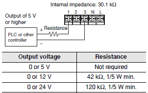
If it is necessary to apply more than 5 V, split the voltage as shown below by inserting resistance in the line to terminal 1 and applying the voltage across terminals 1 and 3. The internal impedance between terminals 1 and 3 is 30.1 kΩ.
For details on G3PW wiring methods, refer to the user's manual.
Reference manual: G3PW Power Controllers User's Manual (Cat. No. Z280)
Comparison with Discontinued Products
The following table compares the G3PX (discontinued products) and G3PW (current products).