Low Voltage Switching Gears
|
|
Features |
| Principles | Classifications |
| Engineering Data | Further Information |
|
|
Troubleshooting |
FAQs about Magnetic Contactors
What are AC-3 and AC-1 in the magnetic contactor ratings?
They are test conditions for magnetic contactors. They are used as a reference for the appropriate load and endurance of the magnetic contactor. The AC-3 is a load condition assuming a motor load, and the AC-1 is a load condition assuming a resistive (heater) load.
I want to use the relays overseas. Are general relays available with 380 or 400 VAC coil rated voltage?
As with the magnetic contactor (J7KC), the auxiliary relay (J7KCA) can be used at up to 550 VAC or 220 VDC coil rated voltage.
What difference between mirror contact and linked contact?
The mirror contact mechanism is that when welding a-contact (main contact), b-contact of the auxiliary circuit is in open-circuit state even if the excitation of coil is released. In addition the above, on the linked contact, when welding b-contact, a-contact of linked contact is in open-circuit state even if the coil is excited.
The magnetic contactor J7KC is applicable to the mirror contact shown in Attachment F of IEC 60947-4-1. The auxiliary relay J7KCA is applicable to the linked contact shown in Attachment L of IEC 60947-5-1.
To what extent can the J7KC support for the construction of safety categories B to 4?
By connecting two J7KC units in series, up to the safety category 4 can be supported.
The following is the example of the configuration in combination with the safety relay unit G9SA-301.
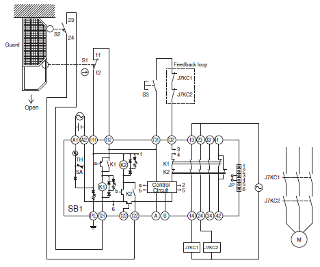
What is the difference between power relay G7Z and magnetic contactor J7KC?
The application is different. J7KC contactor is intended for motor, having an electrical life of over 1,000,000 operations. On the other hand, G7Z is intended for which has low-frequency switching (assumed tripping as rare case), having a electrical life of 80,000 operations.
What is motor capacity the J7KC actually can be applied?
At AC-3 load, upto 2.2 kW (200 to 240 VAC) in Japan, upto 5.5 kW (380 to 440 VAC) in Europe. If a single unit is placed with specified space (10 mm of both side) or more, and the ambient temperature of -10 to 55°C (however, not exceed 35°C of 24 hours a day average temperature), it is usable without derating. If units are mounted by side-by-side, make sure that operational current is 9 A or less.
Why is the rated capacity at 200-240 VAC used under AC-3 load of 2.2 kW (JIS) differ from 3 kW (IEC)?
Because JIS follows trend in the past, and the test conditions and criterias are different from IEC.
"AC-1", "AC-3", "AC-4" and "AC-15"are described. (also, as for DC are described similarly). What does each mean?
"AC-1/AC-3" is descried for main circuit, "C-15" or "AC-12 " are described for auxiliary circuit. Why is the description like this?
Those indicate operational load types. Each application examples are as follows.
AC-1 (AC) switching of resistive load
AC-3 (AC) starting of cage motor, stopping in during operation
AC-4 (AC) starting, plugging*1, inching*2 of cage motor
DC-1 (DC) switching of resistive load
DC-3 (DC) starting, plugging*1, inching*2 of shunt motor 2
DC-5 (DC) starting, plugging*1, inching*2 of series motor 2
*1. Plugging means to quickly change the direction of rotation of a motor, so suppress or reverse the rotation.
*2. Inching means to repeatedly start a motor with reduced amount of power.
The auxiliary circuit is mainly used for control, and AC-15, AC-12, etc. show the load type used for the control switch element.
We would like to open/close the heater with the auxiliary contact. Let us know maximum A which is applicable.
Depending on inductive component, it is shown as follows that according to operational voltage. If inductive component is large, it must be reduced. In all cases, make sure the current when closing or tripping is 30 A or less.
100 to 120 VAC/200 to 240 VAC: 3 to 6 A
24 VDC: 2 to 3 A
48 VDC: 1 to 2 A
What do the rated code "A600" and "Q300" of auxiliary contact mean?
It is the contact rating, in which the alphabet indicates the rated current and the number indicates the rated voltage.
A600 means AC contact rating 10 A 600 V and Q300 means DC contact rating 2.5 A 300 V.
(AC rating A: 10 A, B: 5 A, C: 2.5 A, D: 1 A)
(DC rating N: 10 A, P: 5 A, Q: 2.5 A, R: 1 A)
FAQs about Thermal Overload Relays
How is a thermal overload relay used?
Thermal overload relay J7TC is used in combination with the magnetic contactor J7KC to protect a motor from overload.
When an overload current flows, the bimetallic strip in the thermal overload relay operates to open the auxiliary contacts (NC contact), and this signal from the thermal overload relay stops the operation of the magnetic contactor.
How does it differ from a circuit breaker that similarly protects against overcurrents?
In principle, a thermal overload relay protects a motor. Therefore, it is generally not used in equipment in which no motor is used. However, the thermal overload relay will also burn out if a short-circuit current exceeding several thousand amperes flows through a circuit, so the entire circuit including the thermal overload relay is protected by a circuit breaker.
How can we select the trip current for overcurrent countermeasure by using thermal overload relay?
Select a thermal overload relay in which full load current (rated current) of the motor is within the settling current range, and turn the adjustment dial to the full load current (rated current) value of the motor. Selection example of thermal overload relay for motor capacity are shown as follows.
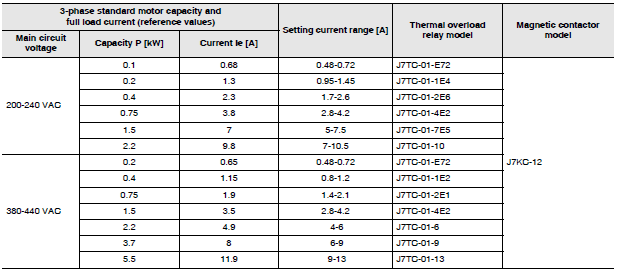
Note: Full load current of 3-phase motor is a reference value. For applicability, check the full load current which you will use.
I heard that the overcurrent of 6 times flows in motor when inrush.
Is there the possibility of thermal and MMS malfunction?
Thermal relays and MMS designed to protect the motor have an operating characteristic that prevents over-current protection from being applied by the current at the start-up of the motor. This characteristic prevents the motor from detecting this current within the range that can be used without burning it for several to several tens of seconds after the start-up.
(Please refer the graph on page 6 shows that the starting current of the motor and the operating characteristics of the thermal overload relay.)
How is thermal phase failure detected?
A special metal strip called bimetal inserted in each phase curves by heat from electric current, and its movement is transmitted to contact part to operate. If a phase failure is occurred, bimetallic strip of 2-phase bimetallic curves by current flow, but which of 1-phase will not curve because current does not flow. This difference is transmitted to the contact part and operate it.
What is the difference between the 1E, 2E, and 3E thermal relays?
What is the equivalent of MMS?
The elements to be detected differ as follows.
1E: overload
2E: overload, failure phase
3E: overload, failure phase, reverse phase
MMS model J7MC is equivalent to 2E.
What is the recommended method for connection of thermal overload relay and electric magnetic contactor?
Connect the b-contact of thermal overload relay to control coil of magnetic contactor.
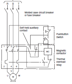
FAQs about Manual Motor Starter
Where is a MMS used?
It is used in motor branch circuits of various machine tools and machines to provide optimal overload, phase failure, and short circuit protection.
What are the space benefits of using MMS?
Compared to the conventional configuration, which combines molded case circuit breaker, magnetic contactor and thermal overload relay, the MMS can significantly reduce the occupied area occupied to less than 50%.
How does it differ from a wiring circuit breaker?
The basic functions of overload and short circuit protection are the same as those of a circuit breaker, but it differs significantly from a circuit breaker in the following points.
(1) Compact with a high breaking capacity
(2) Overload and phase failure protection of a three-phase motor are possible with a thermal bimetallic trip mechanism and a differential amplifier link mechanism
(3) AC-3 switching performance
What is the endurance of MMS?
100,000 cycles for both electrical/mechanical endurance.
What is the equivalent thermal overload relay in terms of operating characteristics?
The MMS three-phase overload characteristics correspond to the operating characteristics of the OMRON thermal overload relay J7TC.
What are the differences in the MMS handle types?
The J7MC-3P is a locker switch (standard type). The J7MC-3R is a rotary switch (High performance type) with improved visibility for operation and display.
What are the MMS accessories?
An auxiliary contact unit (J73MC-W) and alarm contact unit (J73MC-K) are available.
The following combinations are available.
Table of accessory combinations
Mounting position of accessories

Is it applicable to a single-phase motor?
To apply it to a single-phase motor, connect the MMS to three-phase power as shown in Figure C below. If all phases are not energized, the operating current will be low and the motor will not operate normally. If only two phases are connected as shown in Figures A and B, the phase function operates at 5% lower current, as defined in the IEC standard.
Therefore, the normal operating range can be achieved by increasing the value set on the variable adjustment dial by 5%.(See Table 1)
As with a normal circuit breaker, no correction is required when it is used at a load of 80% or less of the rated current of the circuit breaker.

What harmonized protection is supported for MMS and magnetic contactors?
Both Type 1 and Type 2 harmonized protection are possible by combining an MMS and magnetic contactor J7KC.
(For type 1 and 2, refer to the Explanation of Terms of MMS.)
How is a test trip used?
A mechanical trip is possible during a sequence check. The MMS can be tripped by pushing the test trip lever to the left while the handle is ON. After completing the sequence check, check the safety before resetting the product.
Does it meet international standards?
Certificated safety standards are as follows.
Certified standard:
IEC 60947-2, IEC 60947-5-1, UL60947-4-1, CSA 22.2 No.60947-4-1,
GB/T 14048.2(CCC), GB/T 14048.5-1(CCC)
Applicable standard: IEC 60947-4-1, GB/T 14048.4(CCC)
What are the markings on the product?
In addition to the model, rated current setting range and instantaneous tripping current value, a (PS)E mark based on the Electrical Appliances and Material Safety Act is displayed on the front of the main unit. The left side of the main unit displays the IEC rating, AC-3 display indicating motor application, Icu and Ics breaking current values, and connected wire size. The right side displays the UL rating. The accessories display a circuit diagram on the top, and a circuit diagram, rated specifications, and connected wire size on the side.
Is it compliant with IEC 60947-3?
IEC 60947-3 is a standard for switchgear and does not apply to MMS. However, since it conforms to IEC 60947 Isolation, it can be applied as IEC 60204-1 "Power Switchgear".
What is the protective structure of the terminals?
The J7MC has IP20 (finger protection) protective structure with no contact to conducting parts by the test finger specified in IEC 60529 in both terminal (insertion) holes and release holes.
What does "conforms to Isolation" mean?
It means that in response to the requirements that the main contacts of the main unit are closed and the handle (1) does not indicate OFF and (2) cannot be unlocked at this time, the mechanical electrical equipment satisfies the electrical equipment standard IEC 60204-1 "Power Switchgear".
Is there a product lineup of combination starters that combine MMS and contactor (magnetic contactor)?
Combination starter so makes its height direction (between the ducts) longer, that space efficiency becomes worse when installing other products on the control panel. Therefore, OMRON have no line-up of combination starter for the low voltage switch gear. If the combination starter is required, combine the magnetic contactor and MMS on the control panel.
Where should I confirm tripping characteristics and short circuit current due to MMS overcurrent?
For the tripping characteristics of overcurrent, refer to rated current In and current setting range/rated operating current Ie.
Current operating current Ie is set by variable adjustment dial. For the current that can be instantaneously shut off when the short circuit current flows, refer to Instantaneous trip current. For actual performance for short circuit current, refer to the rated breaking capacity (rated limit breaking capacity Icu and rated operating breaking capacity Icu).
What is the difference between Icu and Ics in MMS breaking performance? What is shut-off duty?
These are short circuit current capacities that can be interrupted, but Ics can be used continuously after one interruption (however, replacement is required after the second interruption), whereas Icu is a capacity that can be safely interrupted (when the second interruption is interrupted, it cannot be energized and must be replaced). The shut-off duty is a condition that must be operated in a test assuming a short circuit accident.
Icu requires operating condition that trips current in state the load circuit short circuit current flows at contact ON (O duty) and several minutes later to turn contact ON, and immediately trips the current (CO duty).
The operation condition at Ics is that the contact goes ON at Icu and tripping operation is immediately repeated twice.
What does "Ics=100%Icu (Icu=100kA)" mean?
"Icu=100kA" indicate that the Ics is the same value as Icu.
What is the maximum current value that can be shut off repeatedly with MMS manual switch?
It is shown on the Instantaneous trip current described each rated current specification.
How is the MMS specification selected for the motor capacity?
Select the MMS of rated current specification that full load current (rated current) is within the range of setting operating, set the adjustment dial to the full load current (rated current) of the motor.
The table below shows an example of MMS selection for the motor capacity.
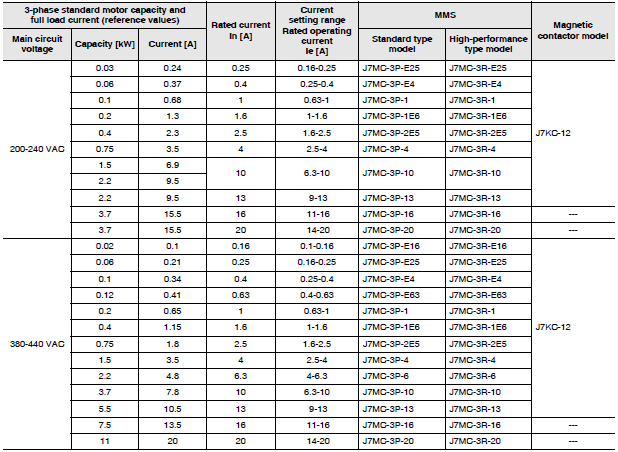
Note: Full load current of 3-phase motor is a reference value. For applicability, check the full load current which you will use.
Can MMS be used to Inverter?
Usage to inverter is allowed. However, make sure to follow the precautions below.
When installing on the power supply side of inverter
When installing the MMS on the input side of the inverter (Fig. 1), select the MMS with the rated current slightly larger than the rated current of the inverter because it is affected by the inverter harmonics. The influence of harmonics varies depending on the length of wires from the inverter. Therefore, it is necessary to check the length on the actual equipment.
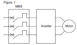
Example of thinking way for selection
(1) The rated current of the MMS should be at least 1.4 times the input current IINV of the inverter.
Note: Note that the input current INV varies depending on existence of DC reactor (DCR) of the inverter.
(2) For the purpose of protection of wires, confirm that the operating characteristics of the MMS is below the thermal characteristics of the wires.
* Measures for false trip.
• Turn the adjustment dial clockwise to increase the settling current.
When installing on the load side of the inverter. A
When installing the MMS on the output side of the inverter (Fig. 2), it is affected by the inverter's harmonics and high frequencies.
These values depending on the length of the wires from the inverter and the carrier frequency. (Since the MMS trips in thermal tripping method by bimetallic element, similar to the thermal overload relay, the operation becomes faster as higher the frequency.) Accordingly, select the MMS after measuring the current value on actual machine at the instaration site. At this time, use a thermoelectric measuring instrument.
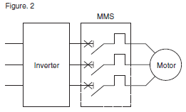
Example of thinking way for selection
(1) Use the thermoelectric instrument to measure the actual current at the site where the MMS is installed, and select the rated current of the MMS.
(2) Confirm that the current is below the thermal characteristics of the motor.
* Measures for false trip.
• Install the power filter for the output circuit on the load side of the inverter.
• Turn the adjustment dial clockwise to increase the settling current.
• Install the wiring from the inverter in the far distance.(close to the motor)
• Lower the carrier frequency. However, the motor noise tends to increase.
• It is recommended that the temperature detecting element be embedded in the winding of the motor to detect the temperature of the winding wire directly as a means of ensuring protection of the motor.
Common FAQs
Described as IP20, how about oil resistance? Is it safe if sebum is attached?
There is no oil resistance. Do not use in an environment where exposed to cutting oil. The sebum is no problem.
What happens if use it at an altitude over 2,000 m?
The insulation property decreases as the air becomes thinner, so operation is not guaranteed.
What happens if I use a stranded wire which is not plated? Or, if not use an insulation stop?
We can't use it because the insulation stop is required for all lines of 1mm2 or less.
Do you have any future development plan?
If stranded wire without plating is used, contact resistance between wire and terminal block will increase, and abnormal heating may occur when current flows. Therefore, the usage is not allowed. If insulation stop is not used, abnormal heating may occur when current flows due to contact failure, or wires may be easily removed.
We have no future development plan. If you do not want to use the insulation stop, use a wire thicker than 1mm2.
How do the motor (3-phases motor) fail?
Most of the failures occur on the stator coil or the bearing. The load applied to the motor becomes heavy due to deterioration or failure of the equipment or device which connected to the motor shaft. In the worst case, the shaft is locked. In such a situation, the overcurrent exceeding the rated current flows through the motor coil, causing abnormal heat generation.
Furthermore, if this state is continued for a long time may result in burn out.