(Unit: mm)
E2E
DC 2-Wire (PUR Cable/Self-diagnosis Output), AC 2-Wire and AC/DC 2-Wire
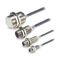
Models with DC 2-Wire (Self-diagnosis Output) and AC 2-Wire added to the lineup
E2E-series DC 2-Wire and 3-Wire Models (2E-X[]D[], E2E-X[]E[], E2E-X[]F[]) have been integrated into the E2E NEXT Series. Refer to the catalog (Cat. No. D120) for details.
Related Contents
- Proximity Sensors
- Features
- Lineup
- Specifications
- Dimensions
- Catalog
last update: November 11, 2024
Tolerance class IT16 applies to dimensions in this data sheet unless otherwise specified.
Sensors
DC 2-Wire
No Self-diagnosis Output, PUR Cable models
Pre-wired Models (Shielded)
E2E-X2D[]-U
E2E-X3D[]-U
E2E-X7D[]-U
E2E-X10D[]-U
Pre-wired Connector Models (Shielded)
E2E-X2D[]-M1TGJ-U
E2E-X3D[]-M1TGJ-U
E2E-X7D[]-M1TGJ-U
E2E-X10D[]-M1TGJ-U
Mounting Hole Dimensions
Self-diagnosis Output models
Pre-wired Models (Shielded)
E2E-X3D1S
E2E-X7D1S
E2E-X10D1S
Pre-wired Models (Unshielded)
E2E-X8MD1S
E2E-X14MD1S
E2E-X20MD1S
Mounting Hole Dimensions
M12 Connector Models (Shielded)
E2E-X3D1S-M1
E2E-X7D1S-M1
E2E-X10D1S-M1
M12 Connector Models (Unshielded)
E2E-X8MD1S-M1
E2E-X14MD1S-M1
E2E-X20MD1S-M1
Mounting Hole Dimensions
AC 2-Wire
Pre-wired Models (Shielded)
E2E-X1R5Y[]
E2E-X2Y[]
E2E-X5Y[]
E2E-X10Y[]
Pre-wired Models (Unshielded)
E2E-X2MY[]
E2E-X5MY[]
E2E-X10MY[]
E2E-X18MY[]
Mounting Hole Dimensions
M12 Connector Models (Shielded)
E2E-X2Y[]-M1
E2E-X2Y[]-M4
E2E-X5Y[]-M1
E2E-X5Y[]-M4
E2E-X10Y[]-M1
M12 Connector Models (Unshielded)
E2E-X5MY[]-M1
E2E-X10MY[]-M1
E2E-X18MY[]-M1
Mounting Hole Dimensions
Connector Pin Arrangement

AC/DC 2-Wire
Pre-wired Models (Shielded)
E2E-X3T1
E2E-X7T1
E2E-X10T1

Mounting Hole Dimensions

Dimensions for Proximity Sensors with Sensor I/O Connectors

Dimensions with the XS2F Connected

last update: November 11, 2024
© Copyright OMRON Corporation 2007 - 2026. All Rights Reserved.