Page top

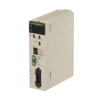
CS1W-CRM21

CS-series CompoNet Master Units

CS1W-CRM21

CS-series CompoNet Master Units Increase the Range of Applicability of Sensors and Actuators.

Communication Specifications

Item Specification
Communications protocol CompoNet Network protocol
Types of communications Remote I/O communications (programless,constant sharing of data with Slave Units)and message
communications (explicit message communications as required with Slave Units and FINS message
communications as required with PLCs)
Baud rate 4 Mbits/s *1,3 Mbits/s,1.5 Mbits/s,93.75 kbits/s
Modulation Base-band
Coding Manchester code
Error control Manchester code rules,CRC
Communications media The following media can be used.*2
Round cable I (JIS C 3306,2-conductor 0.75 mm2)
Round cable II (JIS C3306 4-conductor 0.75 mm2)
Flat Cable I (DCA4-4F10 Standard Flat Cable)
Flat Cable II (DCA5-4F10 Sheathed Flat Cable)
Communications distance
and wiring
Refer to Cable Types,Baud Rates,and Maximum Distances.
Connectable Master Units CompoNet Master Units
Connectable Slave Units CompoNet Slave Units
Maximum I/O capacity Word Slave Units:1,024 inputs and 1,024 outputs (2,048 I/O points total)
Bit Slave Units:256 inputs and 256 outputs (512 I/O points total)
Maximum number of nodes Word Slave Units:64 input nodes and 64 output nodes
Bit Slave Units:128 input nodes and 128 output nodes
Repeater Units:64 nodes
Bits allocated per node
address
Word Slave Units:16 bits
Bit Slave Units:2 bits
Maximum number of nodes
per trunk line or sub-trunk
line
32 nodes (including Repeater Units)
Applicable node addresses Word Slave Units:IN0 to IN63 and OUT0 to OUT63
Bit Slave Units:IN0 to IN127 and OUT0 to OUT127
Repeater Units:0 to 63
Repeater Unit application
conditions
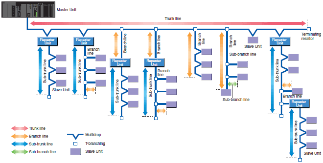
Up to 64 Repeater Units can be connected per network.When Repeater Units are connected in series
from the Master Unit,up to 2 extra segment layers can be created (i.e.,up to 2 Repeater Units are
allowed between a Slave Unit and the Master Unit).
Signal lines Two lines:BDH (communications data high)and BDL (communications data low)
Power lines Two lines:BS+and BS -(power for communications and internal Slave Unit circuits)
Power is supplied from the Master Unit or Repeater Units.
Communications power
supply
24 VDC ± 10%
Connection forms Flat Cable at baud rate of 93.75 kbits/s:No restrictions
Other cables or baud rates:Trunk line and branch lines
Connections for Slave Units and Repeater Units:T-branch or multidrop connections
Remote I/O
communications
Automatic startup when power is turned ON *3 or manual startup using the Remote I/O Communications
Start Switch in I/O Communications Manual Start Mode.
In Registered Slave Unit Participation Standby Mode,communications is not started until all registered
Slave Units are participating in the network.
In Communications Error Communications Stop Mode,communications stop when a communications
error occurs.
I/O communications
manual startup mode
I/O Communications Manual Startup Mode can be set from the CX-Integrater so that remote I/O
communications are not started when the power is turned ON.Remote I/O communications will not start
until the Remote I/O Communications Start Switch is turned ON in memory.
Communications error
communications stop
mode
All remote I/O communications are stopped if a communications error occurs in any Slave Unit.*4
Communications error
input data zero clear mode
All input data will be cleared to zeros in any Slave Unit in which a communications error occurs.
Duplicated Slave address
check
If the same address is set for two different Slave Units or the same memory is allocated to two different
nodes,the Slave Unit that joins communications last will cause a duplicated address error and will leave
the network.The Duplicated Address Error Flag will turn ON.
Registration table The Slave Units that can participate for each node address are registered in a table so that only the
registered Slave Units can participate.If a different Slave Unit attempts to join the network,the
Registration Table Verification Error Flag will turn ON.The Registration Table is generated automatically
or manually edited from the CompoNet Support Software.
Slave Unit
status
Without
registration
table
Participation Flag and Communications Error Flag for each Slave Unit
Participation Flag:Turns ON and remains ON if the Slave Unit joins the network even one time after
system power is turned ON.
Communications Error Flag:Turns ON if the Slave Unit cannot communicate with the Master Unit for any
reason after the Slave Unit has joined the network (i.e.,if the Participation Flag is ON).(Turns OFF when
the error is removed.)
Duplicated Address Error Flags and Alarm Flags
With
registration
table
Participation Flags and Communications Error Flags for each node address for all Slave Units registered
in the Registration Table
Registration Table Verification Error Flags
All Registered Slave Units Participating Flag

Note: 1. Drop-line connections are not supported with a baud rate of 4 Mbits/s, so Slaves with prewired cables (Bit
               Slaves) cannot be used.
           2. Round cable, Flat Cable, and Flat Cable II are all different types of cable. To use more than one type of cable
                 at a time, Repeater Units must be used to separate them on trunk lines and sub-trunk lines.
           3. When power is turned ON to the PLC and the Slave Unit communications power is turned ON. Communications
                 are not started in the following cases:
           4. Communications will not stop for verification errors for registration tables or duplicated address settings.
           5. This error will also occur if a Slave Unit leaves the network and then a different type of Slave Unit joins the
                 network.
           6. The Registered Slave Unit Participation Monitoring Time can be set (verification error check timing).
                Registered Slave Unit Participation Standby Mode can be set. (Remote I/O communications will not start until
                all registered Slave Units are participating.)

Cable Types, Baud Rates, and Maximum Distances

This section provides specifications on the maximum cable length and maximum number of nodes for each type of cable. Do not exceed these specifications.

CS1W-CRM21 Specifications 3

Restrictions (at Baud Rate of 4 Mbits/s (No Branch Lines))

Cable type Maximum length per segment
(maximum length with
Repeater Units)
Branch
line
length
Total branch
line length
per segment
Branch
location
restrictions
Maximum number of
Slave Units per
segment *2
Round cable I 30 m (90 m) 0 m *1 0 m *1 - 32 nodes
Flat Cable I and Flat Cable II
Round Cable II
30 m (90 m) 0 m *1 0 m *1 - 32 nodes

*1. T-branches cannot be connected (only multidrop connections are possible).
*2. Number of nodes including Repeater Units

Restrictions (at Baud Rate of 3 Mbits/s)

Cable type Maximum length
per segment
(maximum
length with
Repeater Units)
Branch
line
length
Total
branch line
length per
segment
Branch
location
restrictions
Maximum
number of
nodes per
branch *1
Sub-
branch
line
length
Total sub-
branch line
length per
segment
Maximum
number
of Slave
Units per
segment *2
Round cable I 30 m (90 m) 0.5 m 8 m 3 branches/m 1 node 0 m 0 m 32 nodes
Flat Cable I
and Flat Cable II
Round Cable II
30 m (90 m) 0.5 m 8 m 3 branches/m 1 node 0 m 0 m 32 nodes

*1. The maximum number of nodes per branch is the maximum number of Slave Units or Repeater Units that can be
       connected to one branch line using multidrop or T-branch connections (sub-branches).
*2. Number of nodes including Repeater Units

Restrictions (at Baud Rate of 1.5 Mbits/s)

Cable type Maximum length
per segment
(maximum
length with
Repeater Units)
Branch
line
length
Total
branch line
length per
segment
Branch
location
restrictions
Maximum
number of
nodes per
branch *1
Sub-
branch
line
length
Total sub-
branch line
length per
segment
Maximum
number
of Slave
Units per
segment *2
Round
cable I
Without
branches
100 m (300 m) 0 m *3 0 m *3 - - - - 32 nodes
With
branches
30 m (90 m) 2.5 m 25 m 3 branches/m 3 nodes 0 m 0 m 32 nodes
Flat Cable I and
Flat Cable II
Round Cable II
30 m (90 m) 2.5 m 25 m 3 branches/m 3 nodes 0.1 m *4 2 m *4 32 nodes

*1. The maximum number of nodes per branch is the maximum number of Slave Units or Repeater Units that can be
       connected to one branch line using multidrop or T-branch connections (sub-branches).
*2. Number of nodes including Repeater Units
*3. T-branches cannot be connected (only multidrop connections are possible).
*4. T-branch connections from sub-branch lines.

Restrictions (at Baud Rate of 93.75 kbits/s)

Cable type Maximum length
per segment
(maximum
length with
Repeater Units)
Branch
line
length
Total
branch line
length per
segment
Branch
location
restrictions
Maximum
number of
nodes per
branch *1
Sub-
branch
line
length
Total sub-
branch line
length per
segment
Maximum
number
of Slave
Units per
segment *2
Round cable I 500 m (1500 m) 6 m 120 m 3 branches/m 1 node - - 32 nodes
Flat Cable I
and Flat Cable II
Round Cable II
No restrictions to a total length per segment of 200 m 32 nodes

*1. The maximum number of nodes per branch is the maximum number of Slave Units or Repeater Units that can be
       connected to one branch line using multidrop or T-branch connections (sub-branches).
*2. Number of nodes including Repeater Units

Specifications

Model CS1W-CRM21
Applicable PLC All CS-series PLCs
Unit classification CS-series Special I/O Unit
Current consumption (Power
supplied from PLC's Power
Supply Unit)
400 mA max.at 5 VDC
Communications power supply
connector
One communications power supply connector for Slave Units and Repeater Units on the trunk line
when using Flat Cable *
Communications power supply
connector allowable current
capacity
5 A max.
Maximum number of mountable
Master Units
One word number assigned:80 Units
Two word numbers assigned:48 Units
Four word numbers assigned:24 Units
Eight word numbers assigned:12 Units
Mounting location According to CS/CJ-series Special I/O Unit specifications.
Communications power ON/OFF
monitoring
The ON/OFF status of the communications power supply can be detected at the communications
power supply connector.
Data stored in Master Unit
(built-in EEPROM)
1)The following device parameters:
Registration Table
Registration Table Check Type
Registered Slave Unit Participation Monitoring Time,Registered Slave Unit Participation Standby
Mode,and Event Disable Setting
Software Settings Table
Communications Error Communications Stop Mode
Communications Error Input Data Zero Clear Mode
Network settings
2)Part of error history (depends on type of error; mainly serious error related to communications
stopping)
Noise immunity Conforms to IEC 61000-4-4 2 kV (applied to PLC power supply).
Vibration resistance 10 to 61.2 Hz with single-amplitude of 0.1 mm,61.2 to 150 Hz and 14.7 m/s2 in X,Y,and Z directions
for 80 min each (sweep time of 8 min × 10 sweeps =80 min)
Shock resistance 196 m/s2 (3 times each in X,Y,and Z directions)
Dielectric strength 1,000 VAC for 1 min,Leakage current:1 mA max.
Between communications connector or external current supply connector and GR terminal on Power
Supply Unit
Between communications connector or external current supply connector and all Unit connectors
Insulation resistance 20 MΩ min.(between isolated circuits)
Ambient operating temperature 0 to 55°C
Ambient operating humidity 10 to 90%(no condensation)
Ambient operating atmosphere No corrosive gases
Storage temperature -20 to 75°C
Weight 190 g max.(Master Unit only)

* The Master Unit does not required communications power.