| Model |
PNP
outputs |
F3SJ-A[][][][]P14 |
F3SJ-A[][][][]P20 |
F3SJ-A[][][][]P30 |
F3SJ-A[][][][]P55 |
NPN
outputs |
F3SJ-A[][][][]N14 |
F3SJ-A[][][][]N20 |
F3SJ-A[][][][]N30 |
F3SJ-A[][][][]N55 |
| Sensor type |
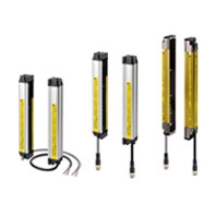
Type 4 safety light curtain |
| Version |
Ver. 2 |
| Setting tool connection |
Connectable |
| Safety category |
Safety purpose of category 4, 3, 2, 1, or B |
| Detection capability |
Opaque objects
14 mm in diameter |
Opaque objects
20 mm in diameter |
Opaque objects
30 mm in diameter |
Opaque objects
55 mm in diameter |
| Beam gap (P) |
9 mm |
15 mm |
25 mm |
50 mm |
| Number of beams (n) |
26 to 140 |
16 to 100 |
10 to 100 |
6 to 50 |
| Protective height (PH) |
245 to 1,271 mm |
245 to 1,505 mm |
245 to 2,495 mm |
270 to 2,470 mm |
| Lens diameter |
Diameter 5 mm |
| Operating range * |
0.2 to 9 m (protective height 1,640 mm max.), 0.2 to 7 m (protective height 1,655 mm min.)
(Depending on the setting tool, the detection distance can be shortened to 0.5 m.) |
Response
time (under
stable light
incident
condition)
(For details,
see
"Response
Time" on
Catalog.) |
ON to OFF |
1 set,
0245 to 983: 11 ms
to 17.5 ms max.
1,055 or higher: 20
ms to 25 ms max. |
1 set,
0245 to 1205: 10 ms
to 15 ms max.
1235 or higher: 17.5
ms to 22.5 ms max. |
1 set: 10 ms to
17.5 ms max. |
1 set: 10 ms to
13 ms max. |
| OFF to ON |
1 set,
0245 to 983: 44 ms
to 70 ms max.
1,055 or higher: 80
ms to 100 ms max. |
1 set,
0245 to 1205: 40 ms
to 60 ms max.
1235 or higher: 70
ms to 90 ms max. |
1 set: 40 ms to
70 ms max. |
1 set: 40 ms to
52 ms max. |
| Startup waiting time |
2 s max. (2.2 s max. for series connection) |
| Power supply voltage (Vs) |
24 VDC ±20% (ripple p-p10% max.) |
Current
consumption
(no load) |
Emitter |
To 50 beams: 76 mA max., 51 to 100 beams: 106 mA max., 101 to 150 beams: 130 mA
max., 151 to 180 beams: 153 mA max., 201 to 234 beams: 165 mA max. |
| Receiver |
To 50 beams: 68 mA max., 51 to 100 beams: 90 mA max., 101 to 150 beams: 111 mA
max., 151 to 180 beams: 128 mA max., 201 to 234 beams: 142 mA max. |
Light source (emitted
wavelength) |
Infrared LED (870 nm) |
Effective aperture angle
(EAA) |
Based on IEC 61496-2. Within ±2.5° for both emitter and receiver when the detection
distance is 3 m or over |
Safety
outputs
(OSSD) |
PNP
outputs |
Two PNP transistor outputs, load current 300 mA max., residual voltage 2 V max. (except
for voltage drop due to cable extension),
allowable capacity load 2.2 μF, leak current 1 mA max.
(This can be different from traditional logic (ON/OFF) because safety circuit is used.) |
NPN
Output |
Two NPN transistor outputs, load current 300 mA max., residual voltage 2 V max. (except
for voltage drop due to cable extension),
allowable capacity load 2.2 μF, leak current 2 mA max.
(This can be different from traditional logic (ON/OFF) because safety circuit is used.) |
Auxiliary
output 1
(Non-safety
output) |
PNP
outputs |
One PNP transistor output, load current 300 mA max., residual voltage 2 V max. (except
for voltage drop due to cable extension),
leak current 1 mA max. |
NPN
Output |
One NPN transistor output, load current 300 mA max., residual voltage 2 V max. (except
for voltage drop due to cable extension),
leak current 1 mA max. |
Auxiliary
output 2
(Non-safety
output.
Function for
Basic
System.) |
PNP
outputs |
One PNP transistor output, load current 50 mA max., residual voltage 2 V max. (except
for voltage drop due to cable extension),
leak current 1 mA max. |
NPN
Output |
One NPN transistor output, load current 50 mA max., residual voltage 2 V max. (except
for voltage drop due to cable extension),
leak current 1 mA max. |
External indicator output
(Non-safety output) |
Available indicators
• Incandescent lamp: 24 VDC, 3 to 7 W
• LED lamp: Load current 10 mA to 300 mA max., leak current 1 mA max.
(To use an external indicator, an F39-JJ3N universal indicator cable or an F39-A01P-PAC
dedicated external indicator kit is required.) |
Output
operation
mode |
Receiver |
Safety output 1, 2: ON when receiving light
Auxiliary output 1: Inverse of safety output signals (Operation mode can be changed with
the setting tool.)
External indicator output 1: Inverse of safety output signals for a basic system (Operation
mode can be changed with the setting tool.), ON when muting/override for a muting
system (Operation mode can be changed with the setting tool.) |
| Emitter |
Auxiliary output 2: Turns ON when the point of 30,000 operating hours is reached
(Operation mode can be changed with the setting tool.)
External indicator output 2: ON when lock-out for a basic system (Operation mode
can be changed with the setting tool.) ON when muting/override for a muting system
(Operation mode can be changed with the setting tool.) |
Input
voltage |
PNP
output |
Test input, Interlock select input, Reset input, Muting input:
ON voltage: 9 V to Vs (short circuit current: approx. 2.0 mA), OFF voltage: 0 to 1.5 V, or
open
External device monitoring input:
ON voltage: 9 V to Vs (short circuit current: approx. 3.5 mA), OFF voltage:open
Note: The Vs indicates a voltage value in your environment. |
NPN
output |
Test input, Interlock select input, Reset input, Muting input:
ON voltage: 0 to 1.5 V (short-circuit current: approx. 1.5 mA), OFF voltage: 9 V to Vs, or
open
External device monitoring input:
ON voltage: 0 to 1.5 V (short-circuit current: approx. 4.0 mA), OFF voltage:open
Note: The Vs indicates a voltage value in your environment. |
| Indicator |
Emitter |
Light intensity level indicators (green LED x 2, orange LED x 3): ON based on the light
intensity
Error mode indicators (red LED x 3): Blink to indicate error details
Power indicator (green LED x 1): ON while power is on
Interlock indicator (yellow LED x 1): ON while under interlock, blinks at lockout.
External device monitoring indicator (muting input 1 indicator), Blanking/test indicator
(muting input 2 indicator) (green LED x 2): ON/flash according to function |
| Receiver |
Light intensity level indicators (green LED x 2, orange LED x 3): ON based on the light
intensity
Error mode indicators (red LED x 3): Blink to indicate error details
OFF output indicator (red LED x 1): ON when safety output is OFF, blinks at lockout.
ON output indicator (green LED x 1): ON while safety output is ON
Muting error indicator, Blanking /test indicator (green LED x 2): ON/flash according to
function |
Mutual interference
prevention function |
Interference light prevention algorithm, detection distance change function |
| Series connection |
Time division emission by series connection
• Number of connections: up to 4 sets (F3SJ-A only) F3SJ-E, F3SJ-B and F3SJ-TS
cannot be connected.
• Total number of beams: up to 400 beams
• Cable length between sensors: 15 m max.
(not including series connection cable (F39-JJR3W or F39-JJR[]L) and power cable)
• Response time under connection: Refer to Catalog |
| Test function |
• Self test (at power-ON and at power distribution)
• External test (emission stop function by test input) |
| Safety-related functions |
• Start interlock, restart interlock (Must be set with a setting tool when the muting function is used.)
• External device monitor
• Muting (Lamp burnout detection, override function included. F39-CN6 key cap for muting is required.)
• Fixed blanking (must be set by a setting tool)
• Floating blanking (must be set by a setting tool) |
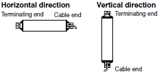
| Connection method |
Connector method (M12, 8-pin) |
| Protective circuits |
Output short-circuit protection, and power supply reverse polarity protection |
| Ambient temperature |
Operating: -10 to 55°C (no icing), Storage: -30 to 70°C |
| Ambient humidity |
Operating: 35% to 85% (no condensation), Storage: 35% to 95% |
Operating ambient light
intensity |
Incandescent lamp: receiving-surface light intensity of 3,000 lx max., Sunlight: receiving-
surface light intensity of 10,000 lx max. |
| Insulation resistance |
20 MΩ min. (at 500 VDC) |
| Withstand voltage |
1,000 VAC 50/60 Hz, 1 min |
| Degree of protection |
IP65 (IEC 60529) |
| Vibration resistance |
Class 3M4 (IEC TR 60721-4-3)
Operation limit: 5 to 150 Hz, Multiple amplitude of 7 mm, Acceleration of 1 G, 10 sweeps each in X, Y, and Z
directions (no delay at resonant frequencies) |
| Shock resistance |
Class 3M4 (IEC TR 60721-4-3)
Operation limit: Acceleration of 15 G, Pulse duration of 6 ms, 100 shocks for each in X, Y, and Z directions (600
shocks in total) |
| Materials |
Casing (including metal parts on both ends): Aluminum, zinc die-cast
Cap: ABS resin, Optical cover: PMMA resin (acrylic), Cable: Oil resistant PVC |
| Net Weight *1 |
Calculate using the following expressions:
(1) For F3SJ-A[][][][][]14, weight (g) = (protective height) x 1.67 + 215
(2) For F3SJ-A[][][][][]20, weight (g) = (protective height) x 1.5 + 217
(3) For F3SJ-A[][][][][]30, weight (g) = (protective height) x 1.41 + 220
(4) For F3SJ-A[][][][][]55, weight (g) = (protective height) x 1.3 + 220 |
| Gross Weight *1 |
Calculate using the following expressions:
(1) For F3SJ-A[][][][][]14, weight (g) = (protective height) x 1.7 + α
(2) For F3SJ-A[][][][][]20/F3SJ-A[][][][][]30, weight (g) = (protective height) x 1.5 + α
(3) For F3SJ-A[][][][][]55, weight (g) = (protective height) x 1.4 + α
The values for α are as follows:
Protected height 245 to 596 mm: = 1,100 protected height 1,660 to 2,180 mm: = 2,400
Protected height 600 to 1,130 mm: = 1,500 protected height 2,195 to 2,500 mm: = 2,600
Protected height 1,136 to 1,658 mm: = 2,000 |
| Accessories |
Instruction manual, standard mounting bracket (F39-LJ1 bracket for top/bottom
mounting), mounting brackets (intermediate) (*),
error mode label, Quick Installation Manual (QIM)
*. Number of intermediate brackets depends on protective height of F3SJ.
• For protective height from 600 to 1,130 mm: 1 set for each of the emitter and receiver
is included
• For protective height from 1,136 to 1,658 mm: 2 sets for each of the emitter and
receiver are included
• For protective height from 1,660 to 2,180 mm: 3 sets for each of the emitter and
receiver are included
• For protective height from 2,195 to 2,500 mm: 4 sets for each of the emitter and
receiver are included |
| Applicable standards *3 |
IEC 61496-1, EN 61496-1, UL 61496-1, Type 4 ESPE (Electro-Sensitive Protective
Equipment)
IEC 61496-2, EN 61496-2, UL 61496-2, Type 4 AOPD (Active Opto-electronic Protective
Devices)
IEC 61508-1 to -3, EN 61508-1 to -3 SIL3
ISO 13849-1: 2015, EN ISO 13849-1: 2015 (PLe/Safety Category 4)
UL 508, UL 1998, CAN/CSA C22.2 No.14, CAN/CSA C22.2 No.0.8 |