| Power supply voltage | A in model number: 100 to 240 VAC, 50/60 Hz
D in model number: 24 VAC, 50/60 Hz; 24 VDC |
|
|---|---|---|
| Operating voltage range | 85% to 110% of rated supply voltage | |
| Power consumption | Models with option selection of 000: 6.6 VA max. at 100 to 240 VAC, and 4.1 VA max. at 24 VAC or 2.3 W max.
at 24 VDC All other models: 8.3 VA max. at 100 to 240 VAC, and 5.5 VA max. at 24 VAC or 3.2 W max. at 24 VDC |
|
| Sensor input | Temperature input
Thermocouple: K, J, T, E, L, U, N, R, S, B, C/W, or PL II Platinum resistance thermometer: Pt100 or JPt100 Analog input Current input: 4 to 20 mA or 0 to 20 mA Voltage input: 1 to 5 V, 0 to 5 V, or 0 to 10 V |
|
| Input impedance | Current input: 150 Ω max., Voltage input: 1 MΩ min.
(Use a 1:1 connection when connecting the ES2-HB-N/THB-N.) |
|
| Control method | ON/OFF control or 2-PID control (with auto-tuning) | |
| Control
output 1/2 |
Relay output | SPST-NO, 250 VAC, 5 A (resistive load), electrical life: 100,000 operations, minimum applicable load: 5 V, 10 mA (reference value) |
| Voltage output
(for driving SSR) |
Output voltage: 12 VDC ±20% (PNP), max. load current: 40 mA, with short-circuit protection circuit
(The maximum load current is 21 mA for models with two control outputs.) |
|
| Linear current
output |
4 to 20 or 0 to 20 mA DC, Load: 500 Ω max., Resolution: Approx. 10,000 | |
| Auxiliary
output |
Number of
outputs |
4 |
| Output
specifications |
SPST-NO relay outputs, 250 VAC, 2 A (resistive load)
Electrical life: 100,000 operations, Minimum applicable load: 10 mA at 5 V (reference values) |
|
| Event
input |
Number of
inputs |
4 or 6 (depends on model) |
| External contact
input specifications |
Contact input: ON: 1 kΩ max., OFF: 100 kΩ min. | |
| Non-contact input: ON: Residual voltage: 1.5 V max., OFF: Leakage current: 0.1 mA max. | ||
| Current flow: Approx. 7 mA per contact | ||
| Transfer
Output |
Number of
outputs |
1 (depends on model): Transfer output type |
| Output
specifications |
Current output: 4 to 20 mA DC, Load: 500 Ω, Resolution: Approx. 10,000
Linear voltage output: 1 to 5 V DC, Load: 1 kΩ min., Resolution: Approx. 10,000 |
|
| RSP
input |
Number of
inputs |
1 |
| Signal type | Current input: 4 to 20 mA, 0 to 20 mA (Input impedance 150 Ω max.)
Voltage input: 1 to 5 V, 0 to 5 V, 0 to 10 V (Input impedance 1 MΩ min.) |
|
| Analog input
scaling |
Scaling of signal to engineering units (EU)
-19999 to 32400 |
|
| Input sampling
period |
50 ms | |
| Setting method | Digital setting using front panel keys | |
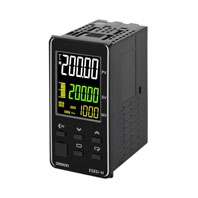
| Indication method | 11-segment digital display, individual indicators, and bar display
Character height: PV: 15.0 mm, SV: 11.0 mm, MV: 7.8 mm Three displays Contents: PV/SV/MV, PV/SV/Bank no., PV/SV/Remaining soak time, etc. Numbers of digits: 5 digits each for PV, SV, and 4 digits for MV |
|
| Bank switching | Supported (number of banks: 8)
Local SP, alarm settings, PID sets (PID constants, MV upper limit, MV lower limit, etc.) |
|
| Other functions | Adaptive control, automatic filter adjustment, water-cooling output adjustment, indication data (power ON time monitor, ambient temperature monitor, and control output ON/OFF count monitors) disturbance suppression (pre-boost), D-AT (disturbance autotuning), parameter masking, operation after power ON, manual output, heating/cooling control, loop burnout alarm, SP ramp, other alarm functions, heater burnout (HB) alarm (including SSR failure (HS) alarm), 40% AT, 100% AT, MV limiter, input digital filter, robust tuning, PV input shift, run/stop, protection functions, extraction of square root, MV change rate limit, logic operations, temperature status display, simple programming, moving average of input value, display brightness setting, banks, high resolution 5 digits 0.01 degree C display and remote SP | |
| Ambient operating
temperature |
-10 to 55°C (with no condensation or icing),
For 3-year warranty: -10 to 50°C with standard mounting (with no condensation or icing) |
|
| Ambient operating
humidity |
25% to 85% | |
| Storage temperature | -25 to 65°C (with no condensation or icing) | |
| Altitude | 2,000 m max. | |
| Recommended fuse | T2A, 250 VAC, time-lag, low-breaking capacity | |
| Installation environment | Overvoltage category II, Pollution Degree 2 (EN/IEC/UL 61010-1) | |