Question
The Relay will not reset. What are the probable causes?
Answer
Probable Causes:
There are probable causes on the contact side (output side) and on the coil side (input side).
Contact-side (Output-side) Causes:
1.Contact Fusing
Excessive current flows to the contacts, and the resulting heat generated causes the contacts to melt, and then stick together inseparably. This occurs when the contacts circuit short-circuits or when a load to which excessive inrush current flows is switched.
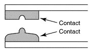
2.Contact Transfer (Shift and Locking)
One contact melts or evaporates and transfers to another contact. Generally, the positive side is concave and the negative side is convex. The concave and convex portions will stick together and become inseparable. This problem depends on usage conditions when switching lamp loads and capacitor loads to which excessive inrush current flows or when using AC loads.
3.Contact Sticking
4.Penetration of Adhesive Material
Flux, coating, or other substance penetrates the Relay and forms an adhesive material that sticks to the Relay drive section and makes it mechanically immobile.
Coil-side (Input-side) Causes:
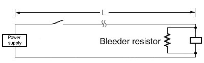
1.Long Wiring Distance with Coil and Power Supply
If the wiring distance (L) from the power supply is long, be sure to measure the voltage on both sides of the Relay coil terminal, and set the power supply voltage so that the rated voltage is applied.
If wiring is performed over a long distance in parallel with power lines, voltage may be generated on both sides of the Relay from the floating capacity of the wires and cause reset failures when the coil input power supply is OFF. If this happens, connect a bleeder resistor to both sides of the coil.
Reference Information:
Bleeder Resistance for MY4 at 100/110-VAC
| Floating capacity (µF) | Resistance (kΩ) | Wattage |
| 0.05 max. | Not required | --- |
| 0.05 to 0.15 | 7 | 2 |
| 0.15 to 0.17 | 6 | 2.5 |
| 0.17 to 0.19 | 5 | 3 |
| 0.19 to 0.23 | 4 | 4 |
| 0.23 to 0.30 | 3 | 5 |
| 0.30 to 0.42 | 2 | 8 |
| 0.42 min. | 1 | 15 |
Bleeder Resistance for MY4 at 200/220-VAC
| Floating capacity (µF) | Resistance (kΩ) | Wattage |
| 0.01 max. | Not required | --- |
| 0.01 to 0.12 | 8 | 8 |
| 0.12 to 0.14 | 7 | 9 |
| 0.14 to 0.15 | 6 | 10 |
| 0.15 to 0.18 | 5 | 12 |
| 0.18 min. | 4 | 15 |
Note:
1.CVV cable: Nominal conductor cross-section area: 2 mm2 (7 conductors), Floating capacity between wires: 0.15 to 0.25 (μF/km).
2.The resistance wattage values are for reference. Be sure to confirm operation using the actual circuit.
2.Using an Solid-state Relay to Operate a Relay
A few milliamps of leakage current IL flows on the output (load) side even when there is no input signal. Therefore, this leakage current may cause reset failures if it is larger than load reset current. As a leakage current countermeasure, connect a bleeder resistor R in parallel with the load to increase the Solid-state Relay switching current.

E: Load (relays etc.) reset voltage
I: Load (relays etc.) reset current
IL: Leakage current from the Solid-state Relay
Recommended Products
 MY
MY
Best-selling, general-purpose relays that can be selected based on operating environment and application
LY
Power-switching Compact General-purpose Relays
G3PE (Three-phase)
Compact, Slim-profile SSRs with Heat Sinks. Solid State Contactors for Three-phase Heaters Reduced Installation Work with DIN Track Mounting.
Other General Purpose Relays FAQ
-
The Relay does not operate even when voltage is applied. Why is this?
-
We were using G2R General Purpose Relay to turn a solenoid valve ON and OFF, and sparks at the contact damaged the relay after only about 3 months of use. What caused this, and what kind of countermeasure is there for it?
-
A Relay burned out. Why is this?