Question
When LY2N General-purpose Relays are OFF, the indicator is lit slightly. What is the problem and countermeasure for this?
Answer
This problem may be the result of residual voltage caused by float capacitance in the wires or leakage current when Relays is OFF. This may also cause reset failure.
Check with the cable manufacturer for how much float capacitance the cables retain. Also check the amount of leakage current with connected sensor.
If needed, connect a bleeder resistor in parallel with Relays coil.
Example: Countermeasure against Leakage Current when Using Proximity Sensors and Relays
Connect the bleeder resistor and so that the leakage current that normally flows through the load (Relays coil) is by-passed.
| AC Relay | DC Relay | |
| Bleeder resistance connection |  | |
| Formula for calculating resistance | 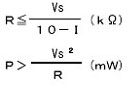 | 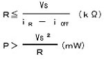 |
| Place these values in the formula | P = Bleeder resistance W (Actual value must be larger by a few multiples.) Vs = Power supply voltage | |
| I = Relay rated current (mA) | iR = Proximity sensor leakage current iOFF = Relay OFF current | |
| Recommended Resistor Value with Margin Not Calculated Using the Formula | At 100 VAC R = 10 KΩ max. P = 3 W (5 W) min. At 200 VAC R = 20 KΩ max. P = 10 W (20 W) min. If heat generation becomes a problem, use the value within the parentheses. | At 12 VDC R = 15 KΩ max. P = 450 mW min. At 24 VDC R = 30 KΩ max. P = 0.1 W min. |
Recommended Products
 MY
MY
Best-selling, general-purpose relays that can be selected based on operating environment and application
LY
Power-switching Compact General-purpose Relays
G3PE (Three-phase)
Compact, Slim-profile SSRs with Heat Sinks. Solid State Contactors for Three-phase Heaters Reduced Installation Work with DIN Track Mounting.
Other General Purpose Relays FAQ
-
The Relay does not operate even when voltage is applied. Why is this?
-
We were using G2R General Purpose Relay to turn a solenoid valve ON and OFF, and sparks at the contact damaged the relay after only about 3 months of use. What caused this, and what kind of countermeasure is there for it?
-
A Relay burned out. Why is this?