General Purpose Relays
|
|
Features |
|
|
|
| Engineering Data |
|
| Explanation of Terms |
|
-
 General Relay Terms
-
 Contact Section
-
 Coil Section
-
 Electrical Characteristics
-
 Problems and Status
-
 Operating Forms
-
 Dimensions and Shapes
-
 PCB Relays
General Relay Terms
Relay
A device designed to cause a sudden, predicted change in a single or multiple electrical output circuits when certain conditions are satisfied by the electrical input circuit that controls the relay device.
Note:
Relays can be classified into electromechanical relays that are used for mechanical operations and static relays that are not.
Based on the operating principles, further classification includes electromagnetic relays, thermal relays, piezo-electric relays (electrostrictive relays), and contactless relays. The IEC classifies relays into all-or-nothing relays, which set and reset based on whether the input quantity is within the operating region or is effectively zero, and measuring relays, which are set when the characteristic quantity with a specified precision reaches the operating value.
DC Relays
Relays designed to operate with a DC input.
AC Relays
Relays designed to operate with an AC input.
Polarized Relays
DC relays that change status depending on the polarity of the control input current.
Note:
There are single-side stable relays, double-sided stable relays, and centrally stable relays.
Relays that are not affected by the polarity of the control input current are called nonpolarized relays (neutral relays).
Sealed Relays
Relays that are completely encased in a container and sealed.
Note:
Generally, sealed relays are sealed in a metal and metal or metal and glass container by welding or similar method.
Enclosed relays are sometimes called sealed relays even though they are simply closed without using welding or similar sealing methods.
Hinged Relays
Hinged relays are classified by the structure of the electromagnet. Hinged relays directly or indirectly switch contacts by the rotating movement of an armature around a fulcrum.
Note:
Hinged relays with armatures that move at right angles to the core axis direction are called side armature type hinged. Those with armatures that move in the direction of the axis are called end-on armature type hinged relays.
Plunger Relays
Plunger relays are classified by the structure of the electromagnet. The armature in a Plunger relay is at the center of the coil and it moves along the coil axis.
Contact Section
Contact Configuration
The contact configuration is called to the contact mechanism.
Types of contacts include NC contacts (break contacts), NO contacts (make contacts), and transfer contacts.
The number of contact poles is referred to the number of contact circuits.
Contact Symbols
The following symbols are used according to the contact mechanism.
| NO contacts | NC contacts | Transfer contacts | MBB contacts | |
| Catalog contact symbols |  |  |  |  |
| JIS contact symbols |  |  |  |  |
Note:
Except for special cases, JIS contact symbols are used in the Technical Explanation for General-purpose Relays and Safety Precautions for All Relays.
Static Relays
Static relays are designed to get a response not from a mechanical operation but rather from an electrical, electromagnetic, or optical action.
Note: Solid-state relays (SSRs) fall into this category.
Flexure is a type of drive method for the contact spring. With flexure-type relays, the contacting force is obtained from a stud, card, or other pushing force.
Lift-off is a type of drive method for the contact spring. After contact, the card or stud separates from the contact spring and the contacting force is derived from the residual bend in the moving spring.
Note: The pressure of a coil spring is also sometimes used.
Contacts that have intersecting bars.

Opposing contact springs act as a pair and a contact is attached to the tip of each spring, which increases the contact reliability.

A moving contact is directly driven a drive mechanism or by part of it. The contact that is not directly driven is called the fixed contact.
A stationary contact is designed for continuous contact.
Note:
Terminals, connectors, etc., fall into this group.
The term "stationary contact" is sometimes used to indicate a fixed contact, the opposite of a moving contact.
Make Contacts (NO Contacts)
The contacts in relays or switches that are normally open and close upon operation are called NO contacts. They are also called front contacts.

Break Contacts (NC Contacts)
The contacts in relays or switches that are normally closed and open upon operation are called NC contacts.
They are also called back contacts.

BBM (Break Before Make) Contacts (Non-shorting Contacts)
BBM contacts are part of the group of contacts that have a specified operating sequence. BBM contacts are a set of contacts in which the contacts that should open at operation open before closing the contacts that need to close.
They are also called transfer contacts.

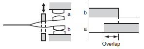
MBB (Make Before Break) Contacts (Shorting Contacts)
MBB contacts are part of the group of contacts that have a specified operating sequence. MBB contacts are a set of contacts in which the contacts that should close at operation close before opening the contacts that need to open.
These are also called continuous contacts.
Contact Springs
Springs for adding contacting force to the contact's contacting section.
The force that operates on a contact to open it.
The operating speed when a closed contact opens.
The gap between a set of contacts when they are open.
Note: This is the shortest distance between two conductors that make up the contacts.
Clearance
The shortest distance between two isolated bare live parts that must be isolated from each other.
Creeping Distance
The shortest distance along the surface of an insulating material placed between two bare live parts that must be insulated from each other.
Double-Throw
A set of contacts that have two contact positions, each of which closes a different circuit. Contact sets consisting of only one contacting position for closing the circuit are called singlethrow contacts.
The sliding action performed after two opposing contacts make contact. This wiping action helps to reduce the impact of film or dust that collects on the surface of contacts.
Rated Load
A standard value for stipulating contact performance, expressed as a combination of contact voltage and contact current.
Rated Carry Current
The current that can be supplied continuously to a contact without exceeding the maximum temperature when the contact is not switching.
The maximum load capacity that can be switched. Design circuits to ensure that this value is not exceeded during operation. The maximum switching capacity is expressed as VA for AC relays and W for DC relays.
The percentage of failures per unit time (or number of operations) during continuous relay switching under individually specified test types and loads.
The failure rate will depend on the switching frequency, the environmental conditions, and the expected reliability level.
Failure rates must always be checked on equipment under real operating conditions.
In this catalog, the failure rate is given as the P level (reference value). This expresses the failure level at a reliability level of 60% (λ 60) (JIS C5003).
| Level | Failure rate(/operation) |
 | |
| L | 5×10⁻⁶ |
| M | 1×10⁻⁶ |
| N | 0.5×10⁻⁶ |
| P | 0.1×10⁻⁶ |
| Q | 0.05×10⁻⁶ |
 |
Example:
λ60 = 0.1×10⁻⁶/operation means that 1 failure can be expected in 10,000,000 operations at a reliability level of 60%.
Contact Resistance
The contact resistance is a combination of the inherent resistance of the conductors that make up the armature, terminals, contacts, and other parts, the boundary resistance where the two contacts meet, and the concentrated resistance.
The contact resistances given in this catalog are the initial specified values. The size of the values does not indicate performance during actual operation.
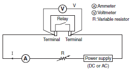
The contact resistance is measured using the voltage drop method (four-terminal method) shown in the following diagram by applying the measurement currents stipulated in the following table.

(The contact resistance for DC relays is the average of measured values for both for forward and reverse polarity.)
Test Currents (JIS C5442)
| Rated current or switched current (A) | Test current (mA) |
| Less than 0.01 | 1 |
| 0.01 or higher but less than 0.1 | 10 |
| 0.1 or higher but less than 1 | 100 |
| 1 or higher | 1,000 |
The maximum value of the contact voltage that can be switched. Never exceed this value during operation.
The maximum value of the contact current that can be switched. Never exceed this value during operation.
Bounce
Undesirable intermittent switching that occurs between contacts when they are turned ON or OFF.
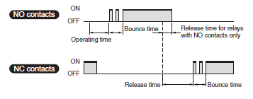
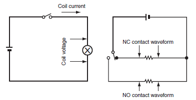
The time that this intermittent switching continues is called the bounce time. The operating time and release time does not include the bounce time.
The problem where an ON contact repeatedly switches due to an external cause. The time that chattering continues is called the chattering time.

The following diagram shows the relationship between bounce and the response of each part when a coil turns ON.

Measurement Circuit
Contacting surfaces cannot be opened easily, even though they are not fused together or mechanically caught.
Note: Gluing occurs easily for contact surfaces of a low hardness that are clean.
Contacting surface and surrounds fuse together and are difficult to open.

Deformation due to contact wear and transfer causes opposing contacting surfaces to become mechanically caught and difficult to open.
Contacting surfaces and the surrounds are affected by electrical discharge or Joule heat and part of the material from one contact transfers to the other opposing contact.

Note: Transfer caused by discharge was previously called large Transfer and Transfer from other causes was called small Transfer.
An arc that transfers contact material from the anode side to the contact surface on the cathode side.
Note: It is said that the direction of the transfer is affected by the contact materials, the balance of heat in a circuit, etc.
An arc that transfers contact material from the cathode side to the contact surface on the anode side.
The problem where the contact resistance drops dramatically for contacts that make contact through a contact film because the contact voltage has exceeded a certain value causing that film to be electrically damaged.
Carbon generated by the electrical switching operation of contacts that attaches to the surface of contacts and causes activation.
A brown or black-brown organic compound in powder form that is created by the reactions of organic gases on contact surfaces.

Note:
Brown powder is generated by the rubbing action of contacts when certain organic gases are present in the operating environment, mainly during switching of platinum contacts, and can cause contact damage.
Sudden loss of insulation due to the voltage applied to two electrodes either side of an insulating material.
Compound Contacts
Contacts made from two or more layers of different materials.
Joined Contacts
Contacts made of two different metals pasted together.
Contacts made using diffusion processing.
Contacts with a multi-layer construction, using plating, joining, or other method.

Plated Contacts
Contacts with plating on the contacting surfaces.
Sintered Contacts
Contacts created using powder metallurgy.
Note: There are various types of these contacts, such as metal sintered contacts and compound sintered contacts.
Inrush Current
A current larger than normal that flows instantaneously or transiently when a contact is closed.

Coil Section
Coil Symbols
The following diagrams are used to indicate the coil drive types.
| Single stable coils | Double-winding latching coils | Single-winding latching coils | ||
| Polarized coils | Non-polarized coils | 4-terminal coils | latching 3-terminal coils | |
 |  |  |  |  |
Rated Voltage
The standard voltage applied to the operating coil when a relay is used under normal conditions.
Rated Current
The standard current that flows to the coil to enable use a relay under normal conditions.
The value is given at a coil temperature of 23°C.
The tolerance, unless otherwise specified in the model specifications, is +15% and −20%.
Coil Resistance
The coil resistance is the resistance between the coil terminals when the coil temperature is 23°C.
The tolerance is ±15% unless otherwise specified in the model specifications.
(The coil resistance for AC specifications and the coil inductance are the reference values.)
The power consumed by the coil when the rated voltage is applied to the coil (rated voltage × rated current).
The rated power consumption for AC specifications is the value at a f60-Hz frequency.
Must-operate Voltage
The minimum voltage required to operate a relay (JIS C5442).
The value is given at a coil temperature of 23°C.
The maximum voltage at which the relay will release when the voltage drops dramatically or gradually (JIS C5442).
The value is given at a coil temperature of 23°C.
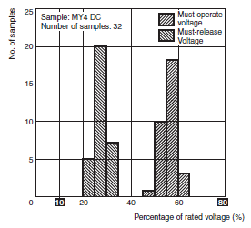
Example: MY4 DC Relay
The distributions of the must-operate voltage and the must-release voltage are shown in the following graph.
As shown in the graph, the relay operates at voltages less than 80% of the rated voltage and releases at voltages greater than 10% of the rated voltage.
Therefore, in this catalog, the operating and must-release voltages are taken to be 80% max. and 10% min. respectively of the rated voltage.
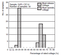
Example: G2R-1 DC Relay
The distributions of the must-operate voltage and the must-release voltage are shown in the following graph.
As shown in the graph, the relay operates at voltages less than 70% of the rated voltage and releases at voltages greater than 15% of the rated voltage.
Therefore, in this catalog, the operating and must-release voltages are taken to be 70% max. and 15% min. respectively of the rated voltage.
The status power is supplied to contacts and the power that has been supplied to the coil is turned OFF then ON. The must-operate voltage at that time is given.
(The coil voltage, contact current, and ambient temperature are set as conditions.)
Minimum Pulse Width
For a latching relay, the minimum pulse width of the rated voltage applied to the coil to set and reset the contacts.
The value is the rated voltage applied to the coil at an ambient temperature of 23°C.
For a DC relay, the value found from the time constant when a rectangular wave is applied.
For an AC relay, the value is given at the rated frequency.
The values are different for operation and release.
A magnetic body inserted in the coil to effectively operate the magnetomotive force in an electromagnet.
Note:
The term core is used mainly for fixed magnetic objects. Those that move inside the coil are called moving cores. Sometimes pole pieces are attached to effectively utilize the magnetic attraction.
A short-circuited coil for partially delaying the change in magnetic flux by using the current generated by mutual inductance between the magnetic pole of a DC electromagnet that has been partially encased and an excitation coil.
Shading coils reduce the vibration of the moving parts.

Electrical Characteristics
Operating Time
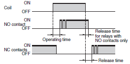
The time between the moment the rated voltage is applied to the coil and when the contacts operate.
For relays with more than one contact, the operating time is the time until the slowest contact operates, unless otherwise defined (JIS C5442).
The operating time is given for a coil temperature of 23°C and does not include bounce time.
Set Time (Latching Relays Only)
The time from the moment when the rated voltage is applied to the set coil until the contacts operate.
For relays with more than one contact, the set time is the time until the slowest contact operates, unless otherwise defined (JIS C5442).
The set time is given for a coil temperature of 23°C and does not include bounce time.
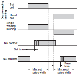
Release Time
The time from the moment the rated voltage is removed from the coil until the contacts release.
For relays with more than one contact, the release time is the time until the slowest contact releases, unless otherwise defined (JIS C5442).
For relays with only NO contacts, the release time is the time until the slowest NO contact opens.
The release time is given for a coil temperature of 23°C and does not include bounce time.
Reset Time (Latching Relays Only)
The time from when the rated voltage is applied to the reset coil until the contacts release.
For relays with NO contacts only, the reset time is the time until the slowest NO contact opens.
For relays with more than one contact, the reset time is the time until the slowest contact releases, unless otherwise specified.
The reset time is given for a coil temperature of 23°C and does not include bounce time.
Bounce
Intermittent switching between contacts due to shock and vibration caused by the impact between the moving parts of relays (armatures) colliding with the core or other contacts (JIS C5442).
The bounce time for NO contacts when the coil rated voltage is applied at a coil temperature of 23°C.
The bounce time for NC contacts when the coil rated voltage is removed at a coil temperature of 23°C.
Number of relay operations per unit time.
Insulation Resistance
The resistance of the isolated sections between contacts and coils, conducting terminals and uncharged metallic parts (e.g., core frame and core), or between contacts.
This value is given for the relay and does not include lands on PCBs.
(1) Between coils and contacts:
Between coil terminals and all contact terminals
(2) Between contacts with different polarity:
Between contact terminals of different polarity
(3) Between contacts with the same polarity:
Between contact terminals with the same polarity
(4) Between set coils and reset coils:
Between set coil terminals and reset coil terminals
Dielectric Strength
The maximum value before insulation damage occurs when voltage is applied for one minute to an isolated metallic part (especially charged metal part).
The voltage is applied at the same location as the insulation resistance.
The leakage current (the current used to detect insulation damage) is normally 1 mA.
Sometimes, however, a leakage current of 3 mA or 10 mA is used.
The maximum abnormal voltage that the relay can withstand when the voltage surges momentarily due to lightning, switching an inductive load, etc.
The surge waveform, unless otherwise specified, is the standard impulse voltage waveform according to JIS C5442,
i.e., 1.2 × 50 μs.
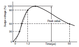
FCC Part 68 specifies 10 × 160 μs ± 1,500 V.
Vibration
categories: Destruction, which quantifies the characteristic changes of, or damage to, the relay due to considerably large vibrations which may develop during the transportation or mounting of the relay, and malfunction durability, which quantifies the malfunction of the relay due to vibrations while it is in operation.
α=0.002f2A×9.8
α : Acceleration of vibration (m/s2)
f : Frequency (Hz)
A : Double amplitude (mm)
Shock
The shock resistance of a relay is divided into two categories:
Destruction, which quantifies the characteristic change of, or damage to, the relay due to considerably large shocks which may develop during the transportation or mounting of the relay, and malfunction durability, which quantifies the malfunction of the relay while it is in operation.
The durability of contacts when no load is applied and the contact is switched at a specified switching frequency.
The durability of contacts when a rated load is applied and the contact is switched at a specified switching frequency.
If different metals are attached at both ends and the temperatures where the metals are connected are held at different temperatures, current will flow in one direction in the circuit.
The electromotive force that causes this current is called thermoelectromotive force.
thermoelectromotive force occurs between the different metals in terminals, armatures, and contacts in relays.
This thermoelectromotive force is the reason the actual temperature and the measured temperature are different when relays are used to switch thermocouples.
Problems and Status
The problem where discharge between opposing conductors causes a short-circuit.
This often occurs with contacts used with medium and large currents.
Welding, locking, or gluing make it difficult to open contacts.
The wear of contacts due to mechanical causes, such as wear during repeated operation.
The expending of contacts due to electrical, thermal, chemical, and other causes during repeated operation.
The problem where contact surfaces become dirty and discharge occurs more easily.
Note:
If precious metal contacts switching in an environment with certain types of organic gases present, the organic gas that attaches to the surface of the contacts will break down as a result of the discharge and create black powder (e.g., carbon), which makes discharge more likely to occur.
Metal oxide, sulfide, and other films that are generated on or attach to contact surfaces and cause boundary resistance.
The magnetic characteristics caused by the shape around directly opposing magnetic surfaces.
Noise due to mechanical vibration caused by AC poles or a rectifier wave drive with insufficient smoothing.
Soak
Removing the difference due to the effect of the magnetic history by applying a saturation current to the operating coil during measurement of the must-operate and must-release voltage (or current) or during testing.
Note: The current that is used is called the soak current.
Operating Forms
Single-stable (Standard) Relays
Relays where the contacts switch based on the non-excitation and excitation of the coil and otherwise have no special functions based on operating elements.
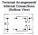
Double-winding Latching Relays
Relays with a set coil and reset coil and a latching configuration to hold the set status or reset status.
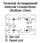
Single-winding Latching Relays
Relays with one coil and a latching configuration that can switch to and hold a set or reset status according to the polarity of the applied voltage.
Stepping Relays
Relays that turn multiple contacts ON and OFF in order each time an input pulse is received.
Ratchet Relays
Relays that perform a type of stepping operation, where the contacts alternate between ON and OFF for each input pulse.
Dimensions and Shapes
Dimensions
For general-purpose relays, the maximum dimensions are listed as guides for design.
Limited to relays characterized by their small size. The maximum dimensions and the average dimensions (indicated in parentheses and marked with an asterisk *) are both indicated as guides for design.
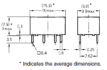
The markings on the relay itself include the model, the voltage specifications, etc., as well as the internal connections. Some small relays do not have internal connections shown on the relay itself.
PCB Relays
High-frequency Isolation
Indicates the degree of high-frequency signal leakage between open contact terminals and unconnected terminals.
Insertion Loss
The loss of a high-frequency signal between closed contact terminals.
Return Loss
The quantity of high-frequency signal reflection that occurs in a transmission path.
V.S.W.R.
The voltage standing-wave ratio that occurs in a transmission path.
Note: Formula for converting return loss to V.S.W.R.

Example Method for Measuring High-frequency Characteristics
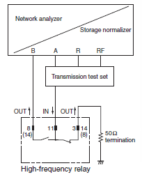
Contacts that are not related to the measurement are terminated at 50 Ω.
Maximum High-frequency Carry Power
The maximum high-frequency signal power that can pass between closed contact terminals.
Maximum High-frequency Switching Power
The maximum high-frequency signal power that a contact can switch. The electrical durability will be shorter than for the rated load.
The degree of high-frequency signal leakage between contact circuits.
The TV rating is one of the common ratings used to evaluate the inrush current resistance characteristics in the UL and CSA standards. It indicates the load switching level for a relay, including the inrush current.
A tungsten lamp is used as the load in the switching test (durability test) and a switching durability of 25,000 times total is required.
| TV rating | Inrush current | Steady-state current | Example models |
| TV-3 | 51 A | 3 A | G2R-1A LY2 G2R-1 (N.O. only) G2R-2 (N.O. only) |
| TV-5 | 78 A | 5 A | G5RL-1A(-E)-LN LY1 |
| TV-8 | 117 A | 8 A | G4W-1112P-US-TV8 G5RL-U1A-E G5RL-K1A-E |
| TV-10 | 141 A | 10 A | G7L G7J (N.O. only) |
| TV-15 | 191 A | 15 A | G4A |
Direction Marks
The marks used mostly on PCB relays to show the coil direction.
This makes it easier to determine the relay coil direction when designing patterns for PCBs and installing PCBs.

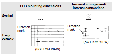
Note:
The external dimensions, PCB mounting dimensions, and terminal arrangement/internal connections all have the direction mark on the left.
JIS contact symbols are not used, in order to match the case markings.
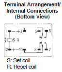
Terminal Arrangement/Internal Connections
1.Top View
Limited to relays with terminal arrangements that can be seen from the top, as shown in the diagram. The internal connections are drawn showing a top view of the relay.

2.Bottom View
Limited to relays with terminals that cannot be seen from the top, as shown in the diagram. The internal connections are drawn showing a bottom view of the relay.

3.Bottom View Rotation Direction
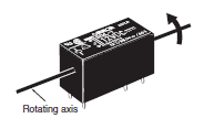
The terminal arrangements for PCB relays are shown with the relay is rotated in the direction of the arrow when the coil is on the left (direction mark on the left).
