General Purpose Relays
OMRON provides General-purpose Relays, I/O Relays, Power Relays, Latching Relays, and Ratchet Relays.
|
|
Features |
|
|
|
| Engineering Data | Further Information |
|
|
|
FAQs
What is the value in parentheses for models with the coil voltage listed as "100/(110) VAC"?
"100/(110) VAC" indicates that the coil has three ratings.
Three Ratings
100 VAC 50 Hz
100 VAC 60 Hz
110 VAC 60 Hz
If the specification is listed as "100/110 VAC," the coil has four ratings, i.e., it also has the following rating:
110 VAC 50 Hz.
For example, the MY and LY Relays have four ratings.
Do the operating and release times include bounce time?
No, they do not.
Operating time:
The time from when power is supplied to the coil until the NO contact (make contact) turns ON.
Release time:
The time from when the coil turns OFF and the NO contact (make contact) turns OFF (or, for transfer contacts, until the NC contact is reached).
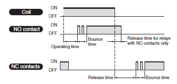
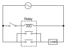
Is the switching capacity doubled if two relays contacts are connected in parallel?
No, it is not.
The two contacts are not always going to turn ON/OFF at the same time (there may be a slight delay) so one contact will bear the full load momentarily.
What are twin-contact relay models suitable for switching minute loads?
The highly reliable crossbar twin contact or twin contact relays are recommended for switching minute loads.
Series Suitable for Minute Loads
Crossbar twin contacts: G7T Series and MY4Z-CBG Series
Twin contacts: MY4Z Series and MK[]ZP Series
How should the contact reliability be viewed in minute load ranges?
The contact resistance of contacts sometimes becomes a problem when switching minute loads.
Sometimes contacts recover during the next operation even if there is random high contact resistance.
The contact resistance may also be increased by the generation of film on the contacts.
Whether or not the contact resistance will cause a problem in the circuit must be a factor used to determine if the contact resistance value constitutes a failure or not. For this reason, only the initial value is specified as reference for contact resistance failure for a relay. Failure rates are expressed as P levels (reference values) with the minimum applicable load used as a guide. Some relay contacts are suitable for minute loads and some are not.
Influence of External Conditions, Environment, and Atmosphere on Relays
Coils
Relationship with Power
(1)For a DC relay, the relationship is as follows:

(2)For an AC relay, the coil impedance must be taken into account because it is affected by the coil inductance.
The coil impedance varies with the frequency. If the characteristic at 60 Hz is 100%, using the same relay at 50 Hz will produce the characteristics shown in the following table.
These values will depend on the type of relay. Check the values before using a relay.
| Rated current, power consumption, and temperature rise | Approx. 117% |
| Must-operate current | Approx. 100% |
| Must-operate voltage and must-release voltage | Approx. 85% |
(3)Be careful of the following points: DC relays, such as keep relays and relays with built-in operation indicators or surge-absorbing diodes, have polarity.
If the relay is connected incorrectly, elements may be destroyed or malfunction.
Applying a DC voltage to an AC relay will cause the coil to heat. This may lead to burning.
Applying an AC voltage to a DC relay will cause the armature to vibrate and the relay will not operate properly.
Relationship with Temperature
Temperature changes affect the resistance of the copper wires used for coils by approximately 0.4% per °C.
This directly affects the relay characteristics because the coil current, which generates the attractive force of an electromagnet, to change.
The effect of temperature on the operating characteristics (such as the must-operate voltage and must-release voltage)
of an AC relay is smaller because the ratio of DC resistance of the coil to the coil impedance is small.
Changes in coil resistance also affect the coil temperature for DC relays. This is because a change in coil current causes the amount of power that is consumed to change. The value of temperature rise changes according to the rate of change in the coil current due to changes in the temperature.
A typical example is shown in the following figure.
This is the percentage of coil temperature rise caused by a 20°C increase in ambient temperature.
Change in coil temperature caused by change in ambient temperature.
Definition of Ambient Temperature
The temperature inside the box increases because of heat generated by the relays and other devices.
The ambient temperature that must be used is the temperature inside the box near the relay.
Electrolytic Corrosion
If the relay coil is not a operating state, exposure to high temperatures or high humidity when there is a potential difference between the coil and other metals, such as the core, may cause the copper wire coil winding to corrode. The corrosion is caused by ionized current passing between the metals when the insulation between them is insufficient.
This can be made analogous to the process of creating metal plating. The effect is accelerated when acid or base is involved.
Not a lot of attention has been paid to this effect in the past; however, recently good quality plastics have been developed for spooling, and insulation materials, such as polyurethane, polyester, polyamide, and fluorine resin, have also been developed for the winding. These modern plastics reduce the effect of electrolytic corrosion.
To prevent electrolytic corrosion, avoid storage in locations with high temperature or high humidity.
Thought must be given to the circuit layout, such as positioning the switch so that the winding is not subject to a constant positive voltage, or create a positive ground.
Good and bad examples are shown on the right.

Operating Time
Relationship between Shape of Relay and operating Time
The operating time of the relay is determined by the coil time constant, delay time due to the moment of inertia, and the contact switching time. These values differ with the shape of the relay. For example, relays with a large gap between the core and the armature or relays that have electromagnets made from materials with a large magnetic resistance, have small inductance values, and the time constant is small. However, this weakens the attractive force, hence more time is required to attract the armature. This phenomenon often occurs in DC operation. The magnetic attraction is weakened because it is inversely proportional to the square of the distance between the core and the armature. For high-speed relays, the gap is made smaller and material with high magnetic permeability is used to reduce the amount of coil winding.
In AC operation, a current larger than the rated current is drawn when power is supplied. The shape of the relay is not as relevant as it is for DC operation.
The moment of inertia has an indirect driving force that prevents large loads on the armatures when they begin to move.
Movement of the armature practically dictates the contact switching time. For this reason, the load and the attractive force must be balanced so that the armature movement is as small as possible, and it moves smoothly through all stages of the movement. Contact bounce is affected by factors such as the moving speed of the armature, quality of the moving parts, and springiness of the contact springs.
Generally, the shape of the contact spring, the contact segment, or the structure of the stopper is designed to dampen the shock from the movement.
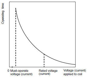
Relationship between Voltage/Current Applied to Coils and Operating Time
The relay operating time is affected by the voltage/current applied to the coils.
As shown in the following figure, when a voltage slightly higher than the must-operate voltage is applied, the time taken for the coil current to reach the must-operate current, the time taken for the moving parts to overcome inertia and start moving, and the time taken for the attractive force to overcome the weight of the load and switch the contacts all become longer, therefore the operating time is considerably longer.
When a voltage much higher than the must-operate voltage is applied, all the times become shorter, and therefore the operating time becomes shorter.
The relationship between the voltage applied to the coil and operating time is as explained above, however, the voltage applied to the coil also affects other characteristics. This is why a rated coil voltage is specified.
Relationship between Applied Coil Voltage/Current and Operating Time
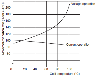
Relationship between Coil Temperature and Operating Time
When the relay temperature changes, the springiness of the relay contact spring, the amount of friction, and the coil resistance change. Of these, the coil resistance has the largest impact on the operating time. As explained in the section on the principles of operation, the movement of the electromagnet is related to the current. The current of DC electromagnets can be expressed by the following equation.
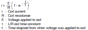
At this point, if the coil temperature rises and the coil resistance increases by 0.4% per °C as stated before. This increases R (the DC coil resistance) of the coil time constant (L/R), therefore reducing the waiting time of the contacts and shortening the operating time. On the other hand, if the coil resistance increases, the coil current decreases. This extends the operating time of the DC relay.
The figure shows the change in operating time according to coil temperature for voltage and current operation.
Large relays that have an operating time of a few 10 ms do not change a lot even if the temperature changes. Small relays that have an operating time of less than 10 ms tend to change more when the temperature changes.
Relationship between Coil Temperature and Operating Time
Operating Environment
Silver Migration
Silver migration occurs when certain humidity and oxidation-reduction conditions exist and an DC voltage is applied to silver electrodes for an extended period of time.
This phenomenon causes the insulation to deteriorate and occasionally causes short-circuit problems.
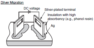
Enlarged Photograph of Silver Migration
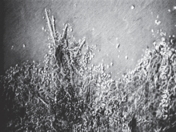
It is not well known what causes silver migration or what conditions accelerate silver migration. However, the following points can be made.
| Conditions that Cause Silver Migration | Conditions that Accelerate Silver Migration |
| Usage of silver | ・ Applied voltage is high and insulation is thin (high potential gradient). ・ High water absorption rate of insulation material ・ Oxidation-reduction gases such as (SO2, H2S, NH3) |
| Applying DC voltage for an extended period of time | |
| Insulation with high absorbency of humidity | |
| Usage in high-temperature or high-humidity environments |
General-purpose relays made by OMRON do not use silver-plated terminals and silver migration will not occur in them.
Cat Whiskers
When a plated part is stored for an extended period of time, needlelike crystals form on the surface. These crystals are called cat whiskers because of their shape. Depending on the length of the crystals, they may cause short-circuit problems.
The reason why cat whiskers are formed is not completely understood. However, it is said that they will form easily when brass or zinc is used as the base material and tin or zinc is used for the plating material.
Example of Whisker Formation

General-purpose relays made by OMRON have hot dip plating or special zinc plating to guard against the formation of whiskers. When designing parts, print boards, or patterns, keep in mind about the use of zinc and brass, and allocate enough space for the insulation.
High-humidity Relays
When shipping relays through tropical zones, regardless whether it is just the relays or the relays are built in to other devices, they will be exposed to high temperatures and high humidity.
To protect the metallic materials from this kind of environment, high-humidity relays with special external specifications have been developed.
Contact Deterioration Due to the Environment
Even if relays are not used and just stored, the degradation of the contacts may progress.
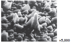
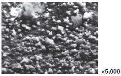
This is due to the influences of sulfur and chlorine contained in the atmosphere, as shown in the following table.
If a relay is to be stored for such a long period as years, it is recommended to perform a conductivity test when the Relay is actually used, or to use Relays with gold-plated or gold-clad contacts.
| Area | Detected elements | Results of observation of contact surfaces (Ag contacts left for 12 months) |
| Chemical plant | Ag and S | Almost uniform and dense corrosive substances were observed on the entire surface of the contacts. As a result of analysis, Ag2S was detected. |
| Steel mill | Ag and S | Irregular projections and recesses were observed and pillars of crystals were dispersed. As a result of analysis, Ag2S was detected . |
| Highway | Ag, S, and CL | Circular crystals were sporadically observed. Ag2S was extremely thin at the white portions, approx. 20 A. |
Chemical Plant
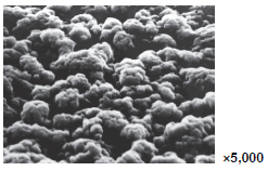
Steel Mill
Highway
Contacts
Inherent Characteristics of Contacts
The desirable features of contacts, purely from a usage point of view, are that they have stable characteristics (such as contact resistance) and that they have a long life. To meet these conditions, contact follow and contact pressure are important aspects.
The contact pressure is normally 5 to 50 g for general-use silver and platinum, and 3 to 10 g for precious metals such as gold, silver, and palladium. The pressure is smaller for precious metals because the switching capacity is smaller and they are relatively robust against environmental influences.
Contact follow requires the contacts to be touching even if the contacts are somewhat worn out. It is closely related to the contact pressure. The product of the two is the workload of the contacts.
For a certain workload, the contact pressure can be increased or the contact follow can be increased to change the contactability.
For example, when the contact pressure is large and the contact follow is small, initially characteristics will appear stable, but as the contact begins to wear out, the contact pressure will rapidly drop and eventually the contacts will not touch at all.
On the other hand, if the contact pressure is small and the contact follow is large, the contact resistance may increase, or it may be difficult to break down the film. Therefore, good relays must have a reasonable balance between contact follow and contact pressure. Contact resistance can be thought of as the concentrated resistance and boundary resistance.
At first glance, the contacts look like they are touching the whole surface. However, depending on the shape and the roughness of the surface of the contacts, they actually touch only on a single or multiple points. Current flow is concentrated at these contact points and the generated resistance is the concentrated resistance.
The contact resistance is related to the contact stiffness, contact pressure, and the inherent resistance of contact material. A model of the contacting parts is shown below. Contact is made over an extremely small area, and current is concentrated in this extremely small area.
A measurement example of the relationship between contact pressure and contact resistance is also shown below.
Current Distribution at Connection Point

Contact Pressure and Contact Resistance
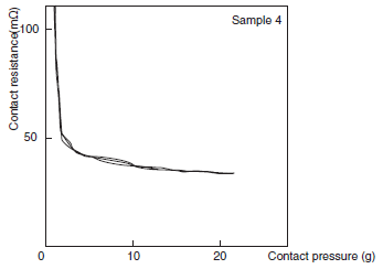
If contacts are exposed to the air, the formation of oxidation and sulphurization films is unavoidable. The resistance caused by these films is called the boundary resistance (film resistance).
Generally, the concentrated resistance makes up a large proportion of the contact resistance before the contacts are used. However, as the contacts are used, arcing and mechanical friction begin to wear them out, and the proportion of the boundary resistance increases.
The proportion depends on the switching frequency.
Contact surfaces subject to higher switching frequencies are relatively clean and the boundary resistance is low. Contacts with low switching frequencies generate films with fairly high boundary resistance.
The contact resistance of a relay is listed in catalogs but it is only a provision of the initial value determined using a standard testing method. The actual contact resistance must be suitable for the application device. Normally it is determined by the tolerance to load impedance. Except for special cases, such as the transmission of sound currents where distortion and attenuation becomes problems, the contact resistance has a tolerance of 1% to 5% of the load impedance.
Load Conditions and Contacts
Most of the problems that occur to a relay are caused by the contactability of the contacts. Load conditions also influence the types of problems that occur.
Load conditions can be grouped into micro-energy level (dry circuit), mid-energy level, and high-energy level conditions.
The micro-energy level in a strict sense is a load condition of a mechanical contact circuit, where the status of the contacts is not affected by heat or discharge. In reality, however, the status of the contacts does not change even when a reasonable voltage is applied, so this load condition is included in the definition.
The voltage level at which the status of the contacts remains unaffected is called the softening voltage. It is 0.09 V for silver, 0.08 V for gold, 0.25 V for platinum, and 0.6 V for tungsten.
The mid-energy level is a load condition where a there is a mild discharge effect. It is from the softening voltage to where arc discharge begins. Flashover begins at 12 V for silver, 15 V for gold, 17.5 V for platinum, 15 V for tungsten, and 11 V for 10% palladium silver alloy.
The high-energy level describes voltages that exceed the arc discharge voltage.
Problems Specific to Contacts
Particular problems can occur depending on how contacts are used. The following describes some of them.
(1) Abnormal Corrosion from Load Switching
This problem occurs when arcing due to load switching bonds nitrogen and oxygen in the atmosphere together to form HNO3, which corrodes metallic materials. (This is called nitric acid corrosion.)
Example of Nitric Acid Corrosion
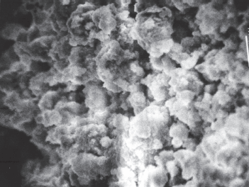
The following countermeasures may be effective.
1. Reduce the amount of arcing that occurs during load switching by creating an arc reduction circuit.
2. Reduce the switching frequency to eliminate continual arcing.
3. Reduce the humidity in the atmosphere.
(2) Coherer Effect
If there is a film on the surface of a contact and the contacts are touching, the film electrically breaks down and the contact resistance drops rapidly when the contact voltage exceeds a certain value.
(3) Thermoelectromotive Force
Relay contacts are made from a combination of metals (such as silver and copper alloy), depending on their function.
The temperature varies between the junctions depending on the distance from the heat-emitting body (such as the coil) and depending on the path of heat conduction. As a result, thermoelectromotive force from a few to a few tens of μV is created between the contact terminals. Care must be taken especially when handling micro signals.
A latching relay (keep relay) can be used to shorten the time required for current to pass through the coil, thus limiting the amount of heat generated by the coil and reducing the thermoelectromotive force. A relay with small thermoelectromotive force can also be used. (These relay have a specially designed contact conduction section.)
Contactability under Load Conditions
The effect on the contacts is completely different between the micro-energy level and high-energy level load conditions. The micro-energy level has little contact wear, but the existence of contact faults becomes a problem. contact wear, welding, and transfer become problems in the high-energy level load condition.
At the micro-energy level, the cleanliness of the contacts is the most important aspect. If any non-conductive material or film is stuck to the contacts, it will cause contact failure.
Non-conductive materials may be dust, such as sand and fibers, but micro-load relays have relatively small contact wipes and pressure so any particles stuck to the contact surfaces will cause contact faults. This is a problem for all relays regardless of the contact material, which makes it difficult to select and use the right relay. Formation of a nonconductive film may be caused by the type of material the relay is made from, or the surrounding environment. The film depends on the moisture in the air, oily or oxidized substances, organic gases emitted from other relays or structures, exhaust gas from vehicles, smoke from factories, flux from soldering, and fingerprints of the assembly worker.
Therefore, strategies are required for the structure of the relay, the material of the contacts, and ambient conditions.
Generic silver contacts oxidize and sulphurize easily.
Oxidized films do not affect the contacts a lot, but sulphurization films have a large effect. For this reason, precious metals that do not sulphurize easily are used. Normally, palladium, gold, or platinum-gold is combined with silver to form silver alloys to use for the contacts.
Contacts made from platinum alloys generate insulating powder (brown powder) due to the unsaturated organic gas that is emitted from benzene, gasoline, and similar substances. Gold does not form any films and the contactability remains stable, but it is soft, so it bends under low pressure. It cannot be used by itself, so palladium may be used to create a double-layer contact where the top layer is a gold film.
In conditions where discharge occurs even with only microloads, the contacts may oxidize or combustible gases in the atmosphere may burn and create a carbonized film.
Carbonized films are not perfect insulators, so the resistance may reach a few ten to a few hundred ohms.
At the high-energy level, flashover continuously generates a lot of energy. This may cause the contacts to melt when they are switching, or the contacts to wear out from scattering of metallic vapor. They may also suffer from problems such as transfer of metallic powder from one contact to the other, or welding where the contacts melt and bond together when power is supplied.
DC voltages and DC currents do not have points that cross at zero like there is for an AC voltage and current. So even for fairly small loads, arcing may continue for a long time.
Under these load conditions, adherence of metallic powder and carbonizing of the insulator may deteriorate the insulation. For this reason, certain types of insulation materials and shapes are chosen. The type of damage that occurs to the contacts depends on the type of load.
Loads such as transformers, motors, and lamps cause large inrush currents and can cause welding of the contacts.
Lamps, motors, transformers, and solenoids cause currents of a few times to multiples of ten times the current.
Inductive loads, such as motors, transformers, and solenoids, cause large reverse currents when power is turned OFF. The voltages reach 4 to 20 times the normal voltage. This may wear out the contacts or damage the load.
Waveform of Induction Motor Starting Current

Waveform of AC Solenoid Starting Current

Waveform of Lamp Starting Current
