Fiber Sensors
|
|
Features |
| Principles | Classifications |
| Engineering Data | Further Information |
|
|
Troubleshooting |
Application and Data
(1) MSR (Mirror Surface Rejection) Function
[Principles]
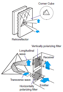
This function and structure uses the characteristics of the Retroreflector and the polarizing filters built into the Retro-reflective Sensors to receive only the light reflected from the Retroreflector.
The waveform of the light transmitted through a polarizing filter in the emitter changes to polarization in a horizontal orientation.
The orientation of the light reflected from the triangular pyramids of the Retroreflector changes from horizontal to vertical.
This reflected light passes through a polarizing filter in the receiver to arrive at the receiver.
[Purpose]
This method enables stable detection of objects with a mirror-like surface.
Light reflected from these types of objects cannot pass through the polarizing filter on the receiver because the orientation of polarization is kept horizontal.
[Examples]
A sensing object with a rough, matte surface (example (2)) can be detected even without the MSR function. If the sensing object has a smooth, glossy surface on the other hand (example (3)), it cannot be detected with any kind of consistency without the MSR function.

[Caution]
Stable operation is often impossible when detecting objects with high gloss or objects covered with glossy film. If this occurs, install the Sensor so that it is at an angle off perpendicular to the sensing object.

(2) Technology for Detecting Transparent Objects Exhibiting Birefringence P-opaquing (Polarization-opaquing)
Conventional methods for detecting transparent objects depend on refraction due to the shape of the sensing objects or on the attenuation of light intensity caused by surface reflection. However, it is difficult to attain a sufficient level of excess gain with these methods. P-opaquing uses the birefringent (double refraction) property of transparent objects to dramatically increase the level of excess gain. The polarization component that is disturbed by the sensing object as they pass along the line is cut by a special and unique OMRON polarization filter. This greatly lowers the intensity of the light received to provide stable detection with simple sensitivity adjustment. "P-opaquing" is a word that was coined to refer to the process of applying polarization in order to opaque transparent objects that exhibit the property of birefringence.

Excellent detection performance with transparent films. (E32-LR11NP + E39-RP1)
The specially designed filter eliminates undesirable light, which allows significantly more light to be interrupted for stable detection of films.
(3) Influence of Fiber Cable Length
The sensing distance listed in the Fiber Units specifications are based on the fiber cable lengths found in the suffix of the model number.
The sensing distance will change if the fiber cable is cut or extended.
The following graph shows the percentage change of the various fiber cable length, where 100% is the sensing distance for a fiber cable with a length of 2 m.
Use this as a guideline for installation distances.
Keep in mind that extending the cable with a fiber connector will result in even shorter sensing distances than the value given in the graph.
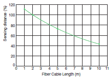
* The 100% value is for a fiber cable with a length of 2 m (same for Through-beam and Reflective Models).
(4) Reflective Models: Sensing Distance Ratios by Workpiece Materials
The following graph shows the percentage change of the various workpieces, where 100% is the sensing distance for white paper, the standard sensing object.
Refer to the value of the material that looks like your workpiece.
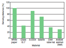
* White paper is 100%.
(5) Surface Color and Light Source Reflectance
Surface Color Reflectance
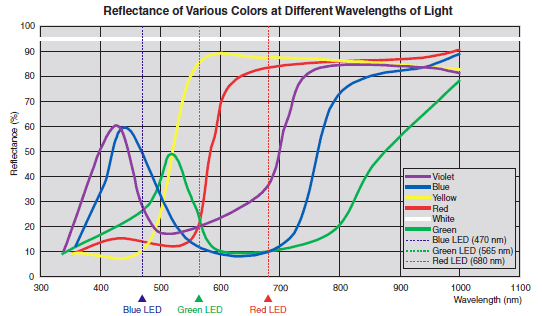
Identifiable Color Marks
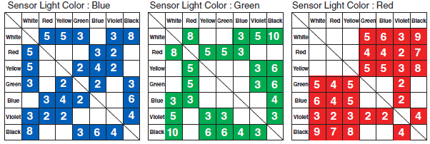
The numbers express the degree of margin (percentage of received light for typical examples).
Models with an white light source support all combinations.
| Sensor light color | Product classification | Model |
 | Fiber Sensors | E3NX-FA, E3NX-MA |
| E3X-HD | ||
| E3X-ZV, E3X-MZV | ||
| E3X-SD | ||
| E3X-NA | ||
 | Fiber Sensors | E3NX-CA |
(6) FAQs
| Category | Question | Answer |
| Fiber Units | Are there any differences between the Fiber Units that are used for emitter and receiver? | With Through-beam Fiber Units, there is no difference between emitter fibers and receiver fibers. With Reflective Fiber Units, the emitter fibers and receiver fibers are different on Coaxial Reflective Models. Emitter fiber cables have identification marks. Refer to the individual dimensions diagrams of Fiber Units for details. |
| What size must the hole be to mount a Threaded or Cylindrical Fiber Unit? | Refer to the recommended mounting hole dimensions given in the catalog. | |
| Are Fiber Cables available in different lengths? | Some models are available with either 5-m or 10-m cable. Ask your OMRON representative for details. | |
| Are these Fiber Units CE certified? | Fiber Units do not have any electrical components and therefore are exempt from CE certification. | |
| What the Fiber Units with built-in lenses? | These highly recommended Fiber Units have built-in lenses that achieve stable detection with high-power beams. | |
| Fiber Amplifier Units | Can the E3X-HD Series be linked with Fiber Amplifier Units from other series? | The E3X-HD Series can be connected with the E3X-DA-S and MDA Series. *1 |
| Can the E3NX-FA Series or E3X-HD Series be operated from a Mobile Console? | Mobile consoles cannot be used with either the E3NX-FA Series or the E3XHD Series. | |
| Can Sensor Communications Units be used with models from the E3NX-FA Series or E3X-HD Series? | If you use E3NX-FA0 Amplifier Units, you can use the E3NW-ECT(EtherCAT), E3NW-CRT(CompoNet) or E3NW-CCL (CC-Link). If you use E3X-HD0 Amplifier Units, you can use the E3X-CRT (CompoNet) or E3X-ECT (EtherCAT).*2 |
*1.E3X-DA-S have been discontinued at the March 2017. E3X-MDA have been discontinued at the August 2021.
*2. E3X-HD0, E3X-CRT and E3X-ECT have been discontinued at the October 2024.