Fiber Sensors
| Introduction | Features |
| Principles | Classifications |
| Engineering Data |
|
|
|
Troubleshooting |
What Is a Fiber Sensor?
A Fiber Sensor is a type of Photoelectric Sensor that enables detection of objects in narrow locations by transmitting light from a Fiber Amplifier Unit with a Fiber Unit.

Features
1. Detection in Narrow Locations
The small sensing section and flexible Fiber Unit cable enable a Fiber Sensor to detect objects in narrow locations.
2. Superior Environmental Resistance
The sensing section of a Fiber Unit has no electric circuits.
This makes it highly reliable even under severe environmental conditions, such as temperature, vibration, shock, water, and electrical noise conditions.
3. Easy Installation
The Fiber Unit can be installed close to the sensing object.
This allows you to freely select where to install the Fiber Amplifier Unit.
4. Virtually No Sensing Object Restrictions
These Sensors operate on the principle that an object interrupts or reflects light, so they are not limited like Proximity Sensors to detecting metal objects. This means they can be used to detect virtually any object, including glass, plastic, wood, and liquid.
5. Fast Response Time
The response time is extremely fast because light travels at high speed and the Sensor performs no mechanical operations because all circuits are comprised of electronic components.
6. Non-contact Sensing
There is little chance of damaging sensing objects or Sensors because objects can be detected without physical contact.
This ensures years of Sensor service.
7. Color Identification
The rate at which an object reflects or absorbs light depends on both the wavelength of the emitted light and the color of the object.
This property can be used to detect colors.
8. Easy Adjustment
Positioning the beam on an object is simple with models that emit visible light because the beam is visible.
Operating Principles
(1) Properties of Light
Rectilinear Propagation
When light travels through air or water, it always travels in a straight line.

Refraction
Refraction is the phenomenon of light being deflected as it passes obliquely through the boundary between two media with different refractive indices.

Reflection (Regular Reflection, Retroreflection, Diffuse Reflection)
A flat surface, such as glass or a mirror, reflects light at an angle equal to the incident angle of the light. This kind of reflection is called regular reflection. A corner cube takes advantage of this principle by arranging three flat surfaces perpendicular to each other. Light emitted toward a corner cube repeatedly propagates regular reflections and the reflected light ultimately moves straight back toward the emitted light. This is referred to as retroreflection.
Most retroreflectors are comprised of corner cubes that measure several square millimeters and are arranged in a precise configuration.
Matte surfaces, such as white paper, reflect light in all directions.
This scattering of light is called diffuse reflection. This principle is the sensing method used by Diffuse-reflective Sensors.

Polarization of Light
Light can be represented as a wave that oscillates horizontally and vertically. Fiber Sensors almost always use LEDs as the light source. The light emitted from LEDs oscillates in the vertical and horizontal directions and is referred to as unpolarized light. There are optical filters that constrain the oscillations of unpolarized light to just one direction. These are known as polarizing filters. Light from an LED that passes through a polarizing filter oscillates in only one direction and is referred to as polarized light (or more precisely, linear polarized light). Polarized light oscillating in one direction (say the vertical direction) cannot pass through a polarizing filter that constrains oscillations to a perpendicular direction (e.g., the horizontal direction). The MSR function on Retro-reflective Sensors operates on this principle.
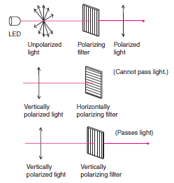
(2) Light Sources
Light Generation (Pulse Modulated light)
The majority of Photoelectric Sensors use pulse modulated light that basically emits light repeatedly at fixed intervals.

Light Source Color and Type
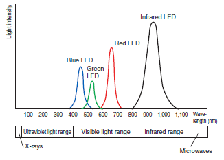
(3) Structure and Principles
Structure
The Fiber Unit has no electrical components whatsoever, so it provides superior resistance to noise and other environmental influences.

Nomenclature (E.g., E3NX-FA21/-FA51)
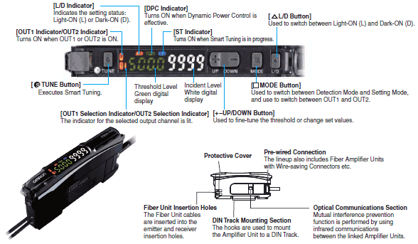
Detection Principles
Optical fiber is comprised of a central core with a high refractive index surrounded by cladding with a low refractive index. When light enters the core, repetitive total internal reflection at the boundary of the less refractive cladding guides the light down the optical fiber. The angle of the light traveling through the optical fiber increases to about 60° by the time the light exits the fiber and strikes a sensing object.
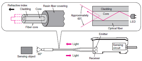
Classification
(1) Classification by Sensing Method
1. Through-beam Sensors
Sensing Method
The emitter and receiver fibers are installed facing each other so that the light from the emitter enters the receiver.
When a sensing object passing between the emitter and receiver fibers interrupts the emitted light, it reduces the amount of light that enters the receiver. This reduction in light intensity is used to detect an object.

Features
Stable operation and long sensing distances ranging from several centimeters to several tens of meters.
Sensing position unaffected by changes in the sensing object path.
Operation not greatly affected by sensing object gloss, color, or inclination.
2. Reflective Sensors
Sensing Method
The emitter and receiver fibers are installed in the same housing and light normally does not return to the receiver.
When light from the emitter strikes the sensing object, the object reflects the light and it enters the receiver where the intensity of light is increased. This increase in light intensity is used to detect the object.

Features
Sensing distance ranging from several centimeters to several meters.
Easy mounting adjustment.
The intensity of reflected light and operating stability vary with the conditions (e.g., color and smoothness) on the surface of the sensing object.
3. Retro-reflective Sensors
Sensing Method
The emitter and receiver fibers are installed in the same housing and light from the emitter is normally reflected back to the receiver by a Reflector installed on the opposite side.
When the sensing object interrupts the light, it reduces the amount of light received. This reduction in light intensity is used to detect the object.

Features
Sensing distance ranges from several centimeters to several meters.
Simple wiring and optical axis adjustment (labor saving).
Operation not greatly affected by the color or angle of sensing objects.
Light passes through the sensing object twice, making these Sensors suitable for sensing transparent objects.
Sensing objects with a mirrored finish may not be detected because the amount of light reflected back to the receiver from such shiny surfaces makes it appear as though no sensing object is present. This problem can be overcome using the MSR function.
4. Limited-reflective Sensors
Detection Method
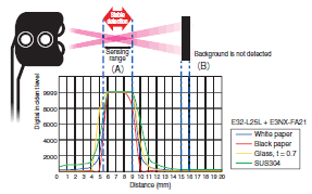
In the same way as for Reflective Sensors, Limited-reflective Sensors receive light reflected from the sensing object to detect it. The emitter and receiver are installed to receive only regular-reflection light, so only objects that are a specific distance (area where light emission and reception overlap) from the Sensor can be detected. In the figure below, the sensing object at (A) can be detected while the object at (B) cannot.
Features
Small differences in height can be detected.
The distance from the Sensor can be limited to detect only objects in a specific area.
Operation is not greatly affected by sensing object colors.
Operation is greatly affected by the glossiness or inclination of the sensing object.
(2) Types of Fiber Cables
Flexible Fibers
The flexible fiber has a small bending radius for easy routing without easily breaking.
It is easy to use because the cable can be bent without significantly reducing light intensity.

Standard Fibers
This fiber have a large bending radius compared with bendresistant or flexible fiber.
Use this fiber where the bending radius is large, or on nonmoving parts.

Break-resistant Fibers
This fiber is resistant to repeated bends for use on moving parts.

Standard Reflective Fiber Units
This structure is standard for most Reflective Fiber Units.
The receiver fiber is located next to the emitter fiber as shown below.

Coaxial Reflective Fiber Units
These Fiber Units offer better detection of small objects at close distances (of 2 mm or less) than Standard Reflective Fiber Units. They also detect glossy surfaces more reliably than Standard Reflective Fiber Units, even if the surface is tilted. The receiver fibers are arranged around the emitter fiber as shown below.

(3) Types of Fiber Units
1. Standard Installation
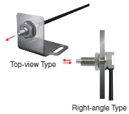
Threaded Models
Standard screw-type installation.
The Fiber Units is mounted into a drilled hole and secured with nuts.
Cylindrical Models
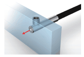
Ideal for installation in narrow spaces.
The Fiber Unit is secured with a set screw.
2. Saving Space
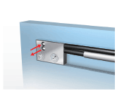
Flat Models
Mount directly in limited spaces without using special mounting brackets.
Sleeve Models (Close-range Detection)
Suitable for close-range detection.
Ideal for detecting minute objects in areas with limited space.
3. Beam Improvements
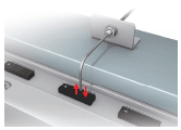
Small-Spot, Reflective (Minute Object Detection)
Small-spot to accurately detect small objects.
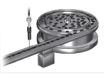
High-power Beam (Long-distance Installation, Dust-resistant)
Suitable for detection on large equipment, of large objects, and in environments with airborne particles
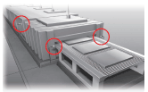
Narrow View (Detection Across Clearance)
The fine beam prevents false detection of light that is reflected off surrounding objects.
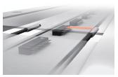
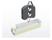
Detection without Background Interference
These Fiber Units detect only objects in the sensing range. Objects in the background that are located beyond a certain point are not detected.
4. Transparent Object Detection
Retro-reflective
Detect transparent objects reliably because the beam passes through the object twice, resulting in greater light interruption.
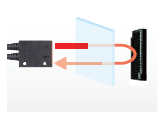
Limited-reflective (Glass Detection)
The limited-reflective optical system provides stable detection of specular reflective glass.
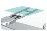
5. Environmental Immunity
Chemical-resistant, Oil-resistant
Made from materials that are resistant to various oils and chemicals.

Bending-resistant, Disconnection-resistant
Resistant to repeated bending on moving parts and breaking from snagging or shock.
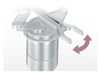
Heat-resistant
Can be used in hightemperature environments at up to 400°C.
6. Special Applications
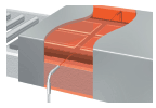
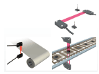
Area Beam (Area Detection)
Detect across areas for meandering materials or falling workpieces whose position vary.
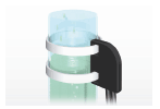
Liquid-level Detection
Detect only liquid when being mounted on tubes or in liquid.
Vacuum-resistant
Can be used under high vacuums of up to 10-5 Pa.
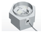
FPD, Semiconductors, and Solar Cells
Designed specifically to reliably detect glass substrates and wafers.

(4) Types of Fiber Amplifier Units
For information on the types of Fiber Amplifier Units and Communications Unit, refer to the product pages on your OMRON website.