

 Global
Ask your OMRON representative for the most recent applicable standards for each model.
CJ3M-CPU3[] / -CPU1[] / CJ2M-MD21[]
CJ-series CJ3M CPU Units, Pulse I/O Modules
![CJ3M-CPU3[] / -CPU1[] / CJ2M-MD21[]](/Images/pf_3984-13-336778-198x198.jpg)
CJ Series continues. And evolves. Ideal for basic equipment upgrades and expansion
Related Contents
- Programmable Controllers
- Features
- Lineup
- Specifications
- Dimensions
- Catalog
last update: October 1, 2026
Applicable standards
CJ3M CPU Units
| Product
name |
Specifications | Current
consumption (A) |
Model | |||||
|---|---|---|---|---|---|---|---|---|
| I/O
capacity |
Program
capacity *1 |
Data
memory capacity |
LD instruction
execution time |
EtherNet/
IP function |
5 V | 24 V | ||
| CJ3M
(Built-in EtherNet/IP) CPU Units  |
5,120
points |
100K steps | 352K words
(DM: 32K words, EM: 32K words × 10 banks) |
0.04 μs | 1 port | 0.91 | 0.003 | CJ3M-CPU35 |
| 50K steps | CJ3M-CPU34 | |||||||
| 20K steps | 64K words
(DM: 32K words, EM: 32K words × 1 bank) |
CJ3M-CPU33 | ||||||
| 10K steps | CJ3M-CPU32 | |||||||
| 5K steps | CJ3M-CPU31 | |||||||
| CJ3M CPU
Units  |
100K steps | 352K words
(DM: 32K words, EM: 32K words × 10 banks) |
--- | 0.26 | 0.003 | CJ3M-CPU15 | ||
| 50K steps | CJ3M-CPU14 | |||||||
| 20K steps | 64K words
(DM: 32K words, EM: 32K words × 1 bank) |
CJ3M-CPU13 | ||||||
| 10K steps | CJ3M-CPU12 | |||||||
| 5K steps | CJ3M-CPU11 | |||||||
*1. The 40K steps allocated to the FB Program Area are not included.
Accessories
The following accessories come with the CPU Unit.
| Product name | Model |
|---|---|
| End Cover | CJ1W-TER01 (must be attached to the right end of the CPU Rack) |
| End Plate | PFP-M (2 required) |
Note: A serial port (RS-232C) connector is not provided. Purchase a connector separately for serial port connection.
Plug: XM3A-0921 (manufactured by OMRON) or equivalent
Hood: XM2S-0911-E (manufactured by OMRON) or equivalent
Power Supply Units
One Power Supply Unit is required for each Rack.
| Product name | Power
supply voltage |
Output capacity | Options | Model | |||||
|---|---|---|---|---|---|---|---|---|---|
| 5-VDC
output capacity |
24-VDC
output capacity |
Total power
consumption |
24-VDC
service power supply |
RUN
output |
Maintenance
forecast monitor |
||||
| AC
Power Supply Unit |
 |
100 to
240 VAC |
5 A | 0.8 A | 25 W | No | No | Yes | CJ1W-PA205C |
 |
Yes | No | CJ1W-PA205R | ||||||
 |
2.8 A | 0.4 A | 14 W | No | No | CJ1W-PA202 | |||
| DC
Power Supply Unit |
 |
24
VDC |
5 A | 0.8 A | 25 W | No | No | CJ1W-PD025 | |
 |
2 A | 0.4 A | 19.6 W | No | No | CJ1W-PD022 | |||
Pulse I/O Modules
Optional Pulse I/O Modules can be mounted to enable pulse I/O. Up to two Pulse I/O Modules can be mounted to the left side of a CJ3M CPU Unit.
| Product
name |
Specifications | Current
consumption (A) |
Model | |
|---|---|---|---|---|
| 5 V | 24 V | |||
| Pulse I/O
Modules  |
Sinking outputs, MIL connector
10 inputs (including four interrupt/quickresponse inputs and two high-speed counter inputs) 6 outputs (including two pulse outputs and two PWM outputs) |
0.08 | --- | CJ2M-MD211 |
| Sourcing outputs, MIL connector
10 inputs (including four interrupt/quickresponse inputs and two high-speed counter inputs) 6 outputs (including two pulse outputs and two PWM outputs) |
0.08 | --- | CJ2M-MD212 | |
Note: Connectors are not provided with Pulse I/O Modules. Purchase the following Connector, an OMRON Cable with Connectors for Connector Terminal Block Conversion Units, or an OMRON Cable with Connectors for Servo Relay Units.
Connecting to Pulse I/O Modules
Refer to the user’s manual for wiring instructions.
| Product name | Specifications | Model | ||
|---|---|---|---|---|
| Applicable
Connector  |
MIL Flat Cable Connectors (Pressure-fitted Connectors)
|
XG4M-4030-T | ||
| Connector-
Terminal Block Conversion Units |
Push-In Plus (Clamp 40-terminals)
 |
XW2K-40G-T | ||
Slim type (M3 screw terminals, 40-terminals)
 |
XW2D-40G6 | |||
Slotted screw (M3 European type, 40-terminals)
 |
XW2R-E40GD-T | |||
Phillips screw (M3 screw terminals, 40-terminals)
 |
XW2R-J40GD-T | |||
| Cable for
Connector- Terminal Block Conversion Unit |
 |
Cable length: 0.25 m | XW2Z-C25K | |
| Cable length: 0.5 m | XW2Z-C50K | |||
| Cable length: 1 m | XW2Z-100K | |||
| Cable length: 1.5 m | XW2Z-150K | |||
| Cable length: 2 m | XW2Z-200K | |||
| Cable length: 3 m | XW2Z-300K | |||
| Cable length: 5 m | XW2Z-500K | |||
| Servo Relay
Units |
Servo Relay Unit for 1 axis
 |
XW2B-20J6-8A | ||
Servo Relay Unit for 2 axes
 |
XW2B-40J6-9A | |||
| Cables for
Servo Relay Units |
G5 Series | Cable for Pulse I/O Modules
 |
Cable length: 0.5 m | XW2Z-050J-A33 |
| Cable length: 1 m | XW2Z-100J-A33 | |||
Servo Driver Connecting Cables
 |
Cable length: 1 m | XW2Z-100J-B31 | ||
| Cable length: 2 m | XW2Z-200J-B31 | |||
| SMARTSTEP2 | Cable for Pulse I/O Modules
 |
Cable length: 0.5 m | XW2Z-050J-A33 | |
| Cable length: 1 m | XW2Z-100J-A33 | |||
Servo Driver Connecting Cables
 |
Cable length: 1 m | XW2Z-100J-B32 | ||
| Cable length: 2 m | XW2Z-200J-B32 | |||
Expansion Racks
Select the I/O Control Unit, I/O Interface Unit, Expansion Connecting Cable, and Power Supply Unit.
CJ-Series I/O Control Unit (Mounted on CPU Rack when Connecting Expansion Racks)
| Product
name |
Specifications | Current
consumption (A) |
Model | |
|---|---|---|---|---|
| 5 V | 24 V | |||
| CJ-Series
I/O Control Unit  |
Mount one I/O Control Unit on the CJ-Series CPU Rack
when connecting CJ-Series Expansion Racks. Connecting Cable: CS1W-CN[][]3 Expansion Connecting Cable Connected Unit: CJ1W-II101 I/O Interface Unit Mount to the right of the CPU Unit. |
0.02 | --- | CJ1W-IC101 |
Note: Mounting the I/O Control Unit in any other location may cause faulty operation.
CJ-Series I/O Interface Unit (Mounted on Expansion Rack)
| Product Name | Specifications | Current
consumption (A) |
Model | |
|---|---|---|---|---|
| 5 V | 24 V | |||
| CJ-Series I/O
Interface Unit  |
One I/O Interface Unit is required on each Expansion Rack.
Connecting Cable: CS1W-CN[][]3 Expansion Connecting Cable Mount to the right of the Power Supply Unit. |
0.13 | --- | CJ1W-II101 |
Note: Mounting the I/O Interface Unit in any other location may cause faulty operation.
I/O Connecting Cables
| Product
name |
Specifications | Model | |
|---|---|---|---|
| I/O
Connecting Cable  |
• Connects an I/O Control Unit on CJ-Series CPU Rack to
an I/O Interface Unit on a CJ-Series Expansion Rack. or • Connects an I/O Interface Unit on CJ-Series Expansion Rack to an I/O Interface Unit on another CJ-Series Expansion Rack. |
Cable length: 0.3 m | CS1W-CN313 |
| Cable length: 0.7 m | CS1W-CN713 | ||
| Cable length: 2 m | CS1W-CN223 | ||
| Cable length: 3 m | CS1W-CN323 | ||
| Cable length: 5 m | CS1W-CN523 | ||
| Cable length: 10 m | CS1W-CN133 | ||
| Cable length: 12 m | CS1W-CN133-B2 | ||
Programming Devices
FA Integrated Tool Package CX-One Ver.4.[]
The CX-One is a comprehensive software package that integrates Support Software for OMRON PLCs and components.
CX-One Version 4.[] includes CX-Programmer and CX-Simulator.
For details, refer to CX-One Ver.4 Catalog (Cat. No. R134).
Optional Products and Maintenance Products
| Product name | Specifications | Model |
|---|---|---|
| Memory Cards | SD memory card, 2 GB | HMC-SD292 |
| SDHC memory card, 4 GB | HMC-SD492 | |
| SDHC memory card, 16 GB | HMC-SD1A2 |
| Product
name |
Specifications | Model | |
|---|---|---|---|
Battery Set
 |
Battery for CJ-series CPU Unit | Battery life 5 years at 25°C
Retains the clock information when power is not supplied. The battery is not built into the CPU unit. |
CJ1W-BAT01 |
End Cover
 |
Mounted to the right-hand side of
CJ-series CPU Racks or Expansion Racks. |
One End Cover is provided as a standard
accessory with each CPU Unit and I/O Interface Unit. |
CJ1W-TER01 |
DIN Track
 |
Length: 0.5 m; Height: 7.3 mm | PFP-50N | |
| Length: 1 m; Height: 7.3 mm | PFP-100N | ||
| Length: 1 m; Height: 16 mm | PFP-100N2 | ||
End Plate
 |
There are 2 stoppers provided with CPU Units and I/O Interface Units
as standard accessories to secure the Units on the DIN Track. |
PFP-M | |
Basic I/O Units
Some discontinued CJ-series Basic I/O Units can still be used with the CJ3M. Please contact your local OMRON sales representative for details.
Input Units
| Unit
classifi- cation |
Product
name |
Specifications | Number
of bits allo- cated |
Response
time *1 |
Current
consum- ption (A) |
Model | |||||
|---|---|---|---|---|---|---|---|---|---|---|---|
| I/O
points |
Input
voltage and current |
Commons | External
connec- tion |
ON | OFF | 5 V | 24 V | ||||
| CJ1
Basic I/O Units |
DC
Input Units  |
8
inputs |
12 to
24 VDC, 10 mA |
Independent
contacts |
Removable
terminal block |
16 *2 | 20
μs max. |
400
μs max. |
0.08 | --- | CJ1W-ID201 |
| 16
inputs |
24 VDC,
7 mA |
16 points,
1 common |
Removable
terminal block |
16 | 20
μs max. |
400
μs max. |
0.08 | --- | CJ1W-ID211 | ||
| 16
inputs [High- speed type] |
24 VDC,
7 mA |
16 points,
1 common |
Removable
terminal block |
16 | 15
μs max. |
90
μs max. |
0.13 | --- | CJ1W-ID212 | ||
| 32
inputs |
24 VDC,
4.1 mA |
16 points,
1 common |
Fujitsu/
OTAX connector |
32 | 20
μs max. |
400
μs max. |
0.09 | --- | CJ1W-ID231
*3 |
||
| 32
inputs |
24 VDC,
4.1 mA |
16 points,
1 common |
MIL
connector |
32 | 20
μs max. |
400
μs max. |
0.09 | --- | CJ1W-ID232
*3 |
||
| 32
inputs [High- speed type] |
24 VDC,
4.1 mA |
16 points,
1 common |
MIL
connector |
32 | 15
μs max. |
90
μs max. |
0.20 | --- | CJ1W-ID233
*3 |
||
| 64
inputs |
24 VDC,
4.1 mA |
16 points,
1 common |
Fujitsu/
OTAX connector |
64 | 120
μs max. |
400
μs max. |
0.09 | --- | CJ1W-ID261
*3 |
||
| 64
inputs |
24 VDC,
4.1 mA |
16 points,
1 common |
MIL
connector |
64 | 120
μs max. |
400
μs max. |
0.09 | --- | CJ1W-ID262
*3 |
||
| AC
Input Units  |
8
inputs |
200 to
240 VAC, 10 mA (200 V, 50 Hz) |
8 points,
1 common |
Removable
Terminal Block |
16 *2 | 10
μs max. |
40
μs max. |
0.08 | --- | CJ1W-IA201 | |
| 16
inputs |
100 to
120 VAC, 7 mA (100 V, 50 Hz) |
16 points,
1 common |
Removable
Terminal Block |
16 | 10
μs max. |
40
μs max. |
0.09 | --- | CJ1W-IA111 | ||
*1. This is the input response time when no filter (i.e., 0 ms) is set.
*2. Although 16 I/O bits (1 word) are allocated, only 8 of these can be used for external I/O.
*3. Either separately purchase and use a 40-pin compatible connector (as listed under Compatible Connectors in the Basic I/O Unit datasheet (Cat. No. G152)), or use OMRON XW2K Series or XW2R-series or G7[]-series I/O Relay Terminal.
Output Units
| Unit
classifi- cation |
Product
name |
Specifications | Number
of bits allo- cated |
Current
consum- ption (A) |
Model | |||||
|---|---|---|---|---|---|---|---|---|---|---|
| Output
type |
I/O
points |
Maximum
switching capacity |
Commons | External
connec- tion |
5 V | 24 V | ||||
| CJ1
Basic I/O Units |
Relay
Contact Output Units  |
--- | 8
outputs |
250 VAC/
24 VDC, 2 A |
Independent
contacts |
Removable
terminal block |
16 *1 | 0.09 | 0.048
max. |
CJ1W-OC201 |
| --- | 16
outputs |
250 VAC/
24 VDC, 2 A |
16 points,
1 common |
Removable
terminal block |
16 | 0.11 | 0.096
max. |
CJ1W-OC211 | ||
| Triac
Output Unit  |
--- | 8
outputs |
250 VAC,
0.6 A |
8 points,
1 common |
Removable
terminal block |
16 *1 | 0.22 | --- | CJ1W-OA201
*2 CJ1W-OA201-1 |
|
| Transistor
Output Units  |
Sinking | 8
outputs |
12 to
24 VDC, 2 A |
4 points,
1 common |
Removable
terminal block |
16 *1 | 0.09 | --- | CJ1W-OD201 | |
| Sinking | 8
outputs |
12 to
24 VDC, 0.5 A |
8 points,
1 common |
Removable
terminal block |
16 *1 | 0.10 | --- | CJ1W-OD203 | ||
| Sinking | 16
outputs |
12 to
24 VDC, 0.5 A |
16 points,
1 common |
Removable
terminal block |
16 | 0.10 | --- | CJ1W-OD211
*3 |
||
| Sinking | 16
outputs [High- speed type] |
24 VDC,
0.5 A |
16 points,
1 common |
Removable
terminal block |
16 | 0.15 | --- | CJ1W-OD213
*3 |
||
| Sinking | 32
outputs |
12 to
24 VDC, 0.5 A |
16 points,
1 common |
Fujitsu/
OTAX connector |
32 | 0.14 | --- | CJ1W-OD231
*4 |
||
| Sinking | 32
outputs |
12 to
24 VDC, 0.5 A |
16 points,
1 common |
MIL
connector |
32 | 0.14 | --- | CJ1W-OD233
*3, *4 |
||
| Sinking | 32
outputs [High- speed type] |
24 VDC,
0.5 A |
16 points,
1 common |
MIL
connector |
32 | 0.22 | --- | CJ1W-OD234
*3, *4 |
||
| Sinking | 64
outputs |
12 to
24 VDC, 0.3 A |
16 points,
1 common |
Fujitsu/
OTAX connector |
64 | 0.17 | --- | CJ1W-OD261
*4 |
||
| Sinking | 64
outputs |
12 to
24 VDC, 0.3 A |
16 points,
1 common |
MIL
connector |
64 | 0.17 | --- | CJ1W-OD263
*4 |
||
| Sourcing | 8
outputs |
24 VDC,
2 A Short- circuit protection |
4 points,
1 common |
Removable
terminal block |
16 *1 | 0.11 | --- | CJ1W-OD202 | ||
| Sourcing | 8
outputs |
24 VDC,
0.5 A Short- circuit protection |
8 points,
1 common |
Removable
terminal block |
16 *1 | 0.10 | --- | CJ1W-OD204 | ||
| Sourcing | 16
outputs |
24 VDC,
0.5 A Short- circuit protection |
16 points,
1 common |
Removable
terminal block |
16 | 0.10 | --- | CJ1W-OD212 | ||
| Sourcing | 32
outputs |
24 VDC,
0.5 A Short- circuit protection |
16 points,
1 common |
MIL
connector |
32 | 0.15 | --- | CJ1W-OD232
*4 |
||
| Sourcing | 64
outputs |
12 to
24 VDC, 0.3 A |
16 points,
1 common |
MIL
connector |
64 | 0.17 | --- | CJ1W-OD262
*4 |
||
*1. Although 16 I/O bits (1 word) are allocated, only 8 of these can be used for external I/O.
*2. CJ1W-OA201 is not UC1 cULus (Class I Division 2 hazardous location certification). If cULus (Class I Div 2 hazardous location certification) is required, use CJ1W-OA201-1.
*3. The ON/OFF response time for the CJ1W-OD213/CJ1W-OD234 is shorter than for the CJ1W-OD211/CJ1WOD233, as shown below.
· ON response time: 0.1 ms improved to 0.015 ms
· OFF response time: 0.8 ms improved to 0.08 ms
*4. Either separately purchase and use a 40-pin compatible connector (as listed under Compatible Connectors in the Basic I/O Unit datasheet (Cat. No. G152)), or use OMRON XW2K Series or XW2R-series or G7[]-series I/O Relay Terminal.
I/O Units
| Unit
classifi- cation |
Product
name |
Specifications | Number
of bits allo- cated |
Current
consum- ption (A) |
Model | |||||
|---|---|---|---|---|---|---|---|---|---|---|
| Output
type |
I/O
points |
Input
voltage, Input current |
Commons | External
connec- tion |
5 V | 24 V | ||||
| Maximum
switching capacity |
||||||||||
| CJ1
Basic I/O Units |
DC Input/
Transistor Output Units 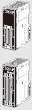 |
Sinking | 16
inputs |
24 VDC,
7 mA |
16 points,
1 common |
Fujitsu/
OTAX connector |
32 | 0.13 | --- | CJ1W-MD231
*2 |
| 16
outputs |
12 to
24 VDC, 0.5 A |
16 points,
1 common |
||||||||
| Sinking | 16
inputs |
24 VDC,
7 mA |
16 points,
1 common |
MIL
connector |
64 | 0.13 | --- | CJ1W-MD233
*2 |
||
| 16
outputs |
12 to
24 VDC, 0.5 A |
16 points,
1 common |
||||||||
| Sinking | 32
inputs |
24 VDC,
4.1 mA |
16 points,
1 common |
Fujitsu/
OTAX connector |
32 | 0.14 | --- | CJ1W-MD261
*1 |
||
| 32
outputs |
12 to
24 VDC, 0.3 A |
16 points,
1 common |
||||||||
| Sinking | 32
inputs |
24 VDC,
4.1 mA |
16 points,
1 common |
MIL
connector |
64 | 0.14 | --- | CJ1W-MD263
*1 |
||
| 32
outputs |
12 to
24 VDC, 0.3 A |
16 points,
1 common |
||||||||
| Sourcing | 16
inputs |
24 VDC,
7 mA |
16 points,
1 common |
MIL
connector |
32 | 0.13 | --- | CJ1W-MD232
*2 |
||
| 16
outputs |
24 VDC,
0.5 A Short- circuit protection |
16 points,
1 common |
||||||||
| TTL I/O
Units  |
--- | 32
inputs |
5 VDC,
3.5 mA |
16 points,
1 common |
MIL
connector |
64 | 0.19 | --- | CJ1W-MD563
*1 |
|
| 32
outputs |
5 VDC,
35 mA |
16 points,
1 common |
||||||||
*1. Either separately purchase and use a 40-pin compatible connector (as listed under Compatible Connectors in the Basic I/O Unit datasheet (Cat. No. G152)), or use OMRON XW2K Series or XW2R-series or G7[]-series I/O Relay Terminal.
*2. Either separately purchase and use 20-pin or 24-pin compatible connector (as listed under Compatible Connectors in the Basic I/O Unit datasheet (Cat. No. G152)), or use OMRON XW2K Series or XW2R-series or G7[]-series I/O Relay Terminal.
Interrupt Input Units
| Unit
classifi- cation |
Product
name |
Specifications | No. of
words allo- cated |
Current
consum- ption (A) |
Model | ||||||
|---|---|---|---|---|---|---|---|---|---|---|---|
| I/O
points |
Input
voltage current |
Commons | Input
pulse width conditions |
Max.
Units moun- table per Unit |
External
connec- tion |
5 V | 24 V | ||||
| CJ1
Basic I/O Units |
Interrupt
Input Unit  |
16
inputs |
24 VDC,
7 mA |
16 points,
1 common |
ON time:
0.05 ms max. OFF time: 0.5 ms max. |
2 | Removable
terminal block |
1 word | 0.08 | --- | CJ1W-INT01 |
Note: An Interrupt Input Unit can be connected only in a CPU Rack. Connect the Interrupt Input Units in slots 0 to 4 on the CPU Rack.
An I/O setting error will occur if an Interrupt Input Unit is connected in other positions on the CPU Rack or to any position on an Expansion Rack. Up to two Interrupt Input Units can be connected.
Quick-response Input Units
| Unit
classifi- cation |
Product
name |
Specifications | Number
of bits allo- cated |
Response
time |
Current
consum- ption (A) |
Model | |||||
|---|---|---|---|---|---|---|---|---|---|---|---|
| I/O
points |
Input
voltage, Input current |
Commons | External
connec- tion |
ON | OFF | 5 V | 24 V | ||||
| CJ1
Basic I/O Units |
Quick-
response Input Unit  |
16
inputs |
24 VDC,
7 mA |
16 points,
1 common |
Removable
terminal block |
16 | 0.05
ms max. |
0.5
ms max. |
0.08 | --- | CJ1W-IDP01 |
Special I/O Units and CPU Bus Units
• Some Special I/O Units and CPU Bus Units are allocated words in the CPU Bus Unit Setup Area.
There may also be limits due to the capacity of the Power Supply Unit that you are using or the maximum number of Units to which memory can be allocated in the CPU But Unit Setup Area.
Refer to the user’s manual for details.
• Some discontinued CJ-series Special I/O Units and CPU Bus Units can still be used with the CJ3M. Please contact your local OMRON sales representative for details.
Process I/O Units
Isolated-type Units with Universal Inputs
| Unit
classifi- cation |
Product
name |
Input
points |
Signal
range selection |
Signal
range |
Conver-
sion speed (resolut- ion) |
Accu-
racy (at ambient temper- ature of 25°C) |
External
connec- tion |
No. of
unit num- bers allo- cated |
Current
consum- ption (A) |
Model | |
|---|---|---|---|---|---|---|---|---|---|---|---|
| 5 V | 24 V | ||||||||||
| CJ1
Special I/O Units |
Process
Input Units (Isolated- type Units with Universal Inputs)  |
4
inputs |
Set
separately for each input |
Universal
inputs: Pt100 (3-wire), JPt100 (3-wire), Pt1000 (3-wire), Pt100 (4-wire), K, J, T, E, L, U, N, R, S, B, WRe5-26, PL II, 4 to 20 mA, 0 to 20 mA, 1 to 5 V, 0 to 1.25 V, 0 to 5 V, 0 to 10 V, ±100 mV selectable range -1.25 to 1.25 V, -5 to 5 V, -10 to 10 V, ±10 V selectable range, potentio- meter |
Resolution
(conversion speed): 1/256,000 (conversion cycle: 60 ms/ 4 inputs) 1/64,000 (conversion cycle: 10 ms/ 4 inputs) 1/16,000 (conversion cycle: 5 ms/ 4 inputs) |
Standard
accuracy: ±0.05% of F.S. |
Remo-
vable terminal block |
1 | 0.30 | --- | CJ1W-PH41U
*1 |
| 4
inputs |
Set
separately for each input |
Universal
inputs: Pt100, JPt100, Pt1000, K, J, T, L, R, S, B, 4 to 20 mA, 0 to 20 mA, 1 to 5 V, 0 to 5 V, 0 to 10 V |
Conversion
speed: 250 ms/ 4 inputs |
Accuracy:
Platinum resistance thermometer input: (±0.3% of PV or ±0.8°C, whichever is larger) ±1 digit max. Thermo- couple input: (±0.3% of PV or ±1.5°C, whichever is larger) ±1 digit max. *2 Voltage or current input: ±0.3% of F.S. ±1 digit max. |
0.32 | --- | CJ1W-AD04U | ||||
*1. Do not connect a Relay Output Unit to the same CPU Rack or to the same Expansion Rack as the CJ1W-PH41U.
*2. L and −100°C or less for K and T are ±2°C ±1 digit max., and 200°C or less for R and S is ±3°C ±1 digit max. No accuracy is specified for 400°C or less for B.
Isolated-type Thermocouple Input Units
| Unit
classifi- cation |
Product
name |
Input
points |
Signal
range selection |
Signal
range |
Conversion
speed (resolution) |
Accuracy
(at ambient tempera- ture of 25°C) |
External
conne- ction |
No. of
unit num- bers allo- cated |
Current
consum- ption (A) |
Model | |
|---|---|---|---|---|---|---|---|---|---|---|---|
| 5 V | 24 V | ||||||||||
| CJ1
Special I/O Units |
Process
Input Units (Isolated- type Thermo- couple Input Units)  |
2
inputs |
Set
separately for each input |
Thermo-
couple: B, E, J, K, L, N, R, S, T, U, WRe5- 26, PLII DC voltage: ±100 mV |
Conversion
speed: 10 ms/ 2 inputs, Resolution: 1/64,000 |
Standard
accuracy: ±0.05% of F.S. (See note 1.) |
Remo-
vable terminal block |
1 | 0.18 | 0.06
(See note 2.) |
CJ1W-PTS15 |
| 4
inputs |
Thermo-
couple: R, S, K, J, T, L, B |
Conversion
speed: 250 ms/ 4 inputs |
Accuracy:
(±0.3% of PV or ±1°C, whichever is larger) ±1 digit max. (See note 3.) |
0.25 | --- | CJ1W-PTS51 | |||||
Note: 1. The accuracy depends on the sensors used and the measurement temperatures. For details, refer to the user’s manual.
Note: 2. This is for an external power supply, and not for internal current consumption.
Note: 3. L and −100°C or less for K and T are ±2°C ±1 digit max., and 200°C or less for R and S is ±3°C ±1 digit max. No accuracy is specified for 400°C or less for B.
Isolated-type Resistance Thermometer Input Units
| Unit
classifi- cation |
Product
name |
Input
points |
Signal
range selection |
Signal
range |
Conversion
speed (resolution) |
Accuracy
(at ambient tempera- ture of 25°C) |
External
connec- tion |
No. of
unit num- bers allo- cated |
Current
consum- ption (A) |
Model | |
|---|---|---|---|---|---|---|---|---|---|---|---|
| 5 V | 24 V | ||||||||||
| CJ1
Special I/O Units |
Process
Analog Input Units (Isolated- type Resistance Thermo- meter Input Units)  |
4
inputs |
Common
inputs |
Resistance
thermo- meter: Pt100, JPt100 |
Conversion
speed: 250 ms/ 4 inputs |
Accuracy:
±0.3% of PV or ±0.8°C, whichever is larger, ±1 digit max. |
Remo-
vable terminal block |
1 | 0.25 | --- | CJ1W-PTS52 |
Isolated-type DC Input Units
| Unit
classifi- cation |
Product
name |
Input
points |
Signal
range selection |
Conversion
speed (resolution) |
Accuracy
(at ambient tempera- ture of 25°C) |
External
connec- tion |
No. of
unit num- bers allo- cated |
Current
consum- ption (A) |
Model | |
|---|---|---|---|---|---|---|---|---|---|---|
| 5 V | 24 V | |||||||||
| CJ1
Special I/O Units |
Isolated-
type DC Input Units  |
2
inputs |
DC
voltage: 0 to 1.25 V, -1.25 to 1.25 V, 0 to 5 V, 1 to 5 V, -5 to 5 V, 0 to 10 V, -10 to 10 V, ±10 V selectable range DC current: 0 to 20 mA, 4 to 20 mA |
Conversion
speed: 10 ms/ 2 inputs Resolution: 1/64,000 |
Standard
accuracy: ±0.05% of F.S. |
Remo-
vable terminal block |
1 | 0.18 | 0.09
*1 |
CJ1W-PDC15 |
*1. This is for an external power supply, and not for internal current consumption.
Analog I/O Units
Analog Input Units
| Unit
classifi- cation |
Product
name |
Input
points |
Signal
range selec- tion |
Signal
range |
Resolu-
tion |
Conver-
sion speed |
Accu-
racy (at ambient tempera- ture of 25°C) |
External
connec- tion |
No. of
unit num- bers allo- cated |
Current
consum- ption (A) |
Model | |
|---|---|---|---|---|---|---|---|---|---|---|---|---|
| 5 V | 24 V | |||||||||||
| CJ1
Special I/O Units |
Analog
Input Units [High- speed type]  |
4
inputs |
Set
sepa- rately for each input |
1 to 5 V
(1/10,000), 0 to 10 V (1/20,000), -5 to 5 V (1/20,000), -10 to 10 V (1/40,000), and 4 to 20 mA (1/10,000) |
20 μs/
1 point, 25 μs/ 2 points, 30 μs/ 3 points, 35 μs/ 4 points |
Voltage:
±0.2% of F.S. Current: ±0.4% of F.S. |
Remo-
vable terminal block |
1 | 0.52 | --- | CJ1W-AD042 | |
| Analog
Input Units  |
8
inputs |
1 to
5 V, 0 to 5 V, 0 to 10 V, -10 to 10 V, 4 to 20 mA |
1/4,000,
(Settable to 1/8,000) *1 |
1 ms/
point max. (Sett- able to 250 μs/ point) *1 |
Voltage:
±0.2% of F.S. Current: ±0.4% of F.S. |
0.42 | --- | CJ1W-AD081-V1 | ||||
| 4
inputs |
0.42 | --- | CJ1W-AD041-V1 | |||||||||
*1. The resolution and conversion speed cannot be set independently. If the resolution is set to 1/8,000, then the conversion speed will be 250 μs/point.
Analog Output Units
| Unit
classifi- cation |
Product
name |
Output
points |
Signal
range selec- tion |
Signal
range |
Resolu-
tion |
Conver-
sion speed |
Accu-
racy (at ambient tempera- ture of 25°C) |
External
connec- tion |
No. of
unit num- bers allo- cated |
Current
consum- ption (A) |
Model | |
|---|---|---|---|---|---|---|---|---|---|---|---|---|
| 5 V | 24 V | |||||||||||
| CJ1
Special I/O Units |
Analog
Output Units [High- speed type]  |
4
outputs |
Set
sepa- rately for each input |
1 to 5 V
(1/10,000), 0 to 10 V (1/20,000), and -10 to 10 V (1/40,000) |
20 μs/
1 point, 25 μs /2 points, 30 μs/ 3 points, 35 μs/ 4 points |
±0.3%
of F.S. |
Remo-
vable terminal block |
1 | 0.40 | --- | CJ1W-DA042V | |
| Analog
Output Units  |
8
outputs |
1 to
5 V, 0 to 5 V, 0 to 10 V, -10 to 10 V |
1/4,000
(Settable to 1/8,000) |
1 ms/
point max (Settable to 250 μs/ point) |
0.14 | 0.14
*1 |
CJ1W-DA08V | |||||
| 8
outputs |
4 to
20 mA |
0.14 | 0.17
*1 |
CJ1W-DA08C | ||||||||
| 4
outputs |
1 to
5 V, 0 to 5 V, 0 to 10 V, -10 to 10 V, 4 to 20 mA |
1/4,000 | 1 ms/
point max. |
Voltage
output: ±0.3% of F.S. Current output: ±0.5% of F.S. |
0.12 | 0.2
*1 |
CJ1W-DA041 | |||||
| 2
outputs |
0.12 | 0.14
*1 |
CJ1W-DA021 | |||||||||
*1. This is for an external power supply, and not for internal current consumption
Analog I/O Units
| Unit
classifi- cation |
Product
name |
No. of
points |
Signal
range selec- tion |
Signal
range |
Resolu-
tion (See note.) |
Conver-
sion speed (See note.) |
Accu-
racy (at ambient tempera- ture of 25°C) |
External
connec- tion |
No. of
unit num- bers allo- cated |
Current
consum- ption (A) |
Model | |
|---|---|---|---|---|---|---|---|---|---|---|---|---|
| 5 V | 24 V | |||||||||||
| CJ1
Special I/O Units |
Analog
I/O Units  |
4
inputs |
Set
sepa- rately for each input |
1 to
5 V, 0 to 5 V, 0 to 10 V, -10 to 10 V, 4 to 20 mA |
1/4,000
(Settable to 1/8,000) |
1 ms/
point (Settable to 500 μs/ point max.) |
Voltage
input: ±0.2% of F.S. Current input: ±0.2% of F.S. |
Remo-
vable terminal block |
1 | 0.58 | --- | CJ1W-MAD42 |
| 2
outputs |
Voltage
output: ±0.3% of F.S. Current output: ±0.3% of F.S. |
|||||||||||
Note: The resolution and conversion speed cannot be set independently. If the resolution is set to 1/4,000, then the conversion speed will be 1 ms/point.
Temperature Control Units
| Unit
classifi- cation |
Product
name |
Specifications | No. of unit
numbers allocated |
Current
consum- ption (A) |
Model | |||
|---|---|---|---|---|---|---|---|---|
| No. of
loops |
Temperature
sensor inputs |
Control
outputs |
5 V | 24 V | ||||
| CJ1
Special I/O Units |
Tempera-
ture Control Units  |
4 loops | Thermocouple
input (R, S, K, J, T, B, L) |
Open
collector NPN outputs |
2 | 0.25 | --- | CJ1W-TC001 |
| 4 loops | Open
collector PNP outputs |
0.25 | --- | CJ1W-TC002 | ||||
| 2 loops,
heater burnout detection function |
Open
collector NPN outputs |
0.25 | --- | CJ1W-TC003 | ||||
| 2 loops,
heater burnout detection function |
Open
collector PNP outputs |
0.25 | --- | CJ1W-TC004 | ||||
| 4 loops | Platinum
resistance thermometer input (JPt100, Pt100) |
Open
collector NPN outputs |
0.25 | --- | CJ1W-TC101 | |||
| 4 loops | Open
collector PNP outputs |
0.25 | --- | CJ1W-TC102 | ||||
| 2 loops,
heater burnout detection function |
Open
collector NPN outputs |
0.25 | --- | CJ1W-TC103 | ||||
| 2 loops,
heater burnout detection function |
Open
collector PNP outputs |
0.25 | --- | CJ1W-TC104 | ||||
High-speed Counter Unit
| Unit
classifi- cation |
Product
name |
Specifications | No. of unit
numbers allocated |
Current
consum- ption (A) |
Model | |||
|---|---|---|---|---|---|---|---|---|
| Countable
channels |
Encoder A and
B inputs, pulse input Z signals |
Max.
counting rate |
5 V | 24 V | ||||
| CJ1
Special I/O Units |
High-
speed Counter Unit  |
2 | Open collector
Input voltage: 5 VDC, 12 V, or 24 V (5 V and 12 V are each for one axis only.) |
50 kHz | 4 | 0.28 | --- | CJ1W-CT021 |
| RS-422 line driver | 500 kHz | |||||||
Note: 1. If interrupts to the CPU Unit are used, mount the Interrupt Input Unit in one of the slots 0 to 4 on the CPU Rack.
Note: 2. Use the CJ1W-CT021 with the lot number 030121 (unit version 1.06) or later when using it in combination with the CJ3 CPU Unit.
Position Control Units
Position Control Units (High-speed type)
| Unit
classifi- cation |
Product
name |
Specifications | No. of
unit numbers allocated |
Current
consum- ption (A) |
Model | ||||
|---|---|---|---|---|---|---|---|---|---|
| Control output interface | No.
of axes |
5 V | 24 V | ||||||
| CJ1
Special I/O Units |
Position
Control Units [High- speed type] *1, *2 |
Pulse-train open-collector output with
Pulse Counter Function |
2
axes |
2 | 0.27 | --- | CJ1W-NC214 | ||
| 4
axes |
0.31 | --- | CJ1W-NC414 | ||||||
| Pulse-train line-driver output with
Pulse Counter Function |
2
axes |
2 | 0.27 | --- | CJ1W-NC234 | ||||
| 4
axes |
0.31 | --- | CJ1W-NC434 | ||||||
| Position
Control Unit Cables |
Open-
collector output |
For
CJ1W-NC214/ NC414 |
Connecting
Servo Drives: G5 Series R88D-KT |
1
axis |
Cable length: 1 m | XW2Z-100J-G13 | |||
| Cable length: 3 m | XW2Z-300J-G13 | ||||||||
| Connecting
Servo Drives: SMARTSTEP2 R7D-BP |
Cable length: 1 m | XW2Z-100J-G16 | |||||||
| Cable length: 3 m | XW2Z-300J-G16 | ||||||||
| Connecting
Servo Drives: G5 Series R88D-KT |
2
axes |
Cable length: 1 m | XW2Z-100J-G5 | ||||||
| Cable length: 3 m | XW2Z-300J-G5 | ||||||||
| Connecting
Servo Drives: SMARTSTEP2 R7D-BP |
Cable length: 1 m | XW2Z-100J-G8 | |||||||
| Cable length: 3 m | XW2Z-300J-G8 | ||||||||
| Line-
driver output |
For
CJ1W-NC234/ NC434 |
Connecting
Servo Drives: G5 Series R88D-KT |
1
axis |
Cable length: 1 m | XW2Z-100J-G9 | ||||
| Cable length: 5 m | XW2Z-500J-G9 | ||||||||
| Cable length: 10 m | XW2Z-10MJ-G9 | ||||||||
| Connecting
Servo Drives: SMARTSTEP2 R7D-BP |
Cable length: 1 m | XW2Z-100J-G12 | |||||||
| Cable length: 5 m | XW2Z-500J-G12 | ||||||||
| Cable length: 10 m | XW2Z-10MJ-G12 | ||||||||
| Applicable
Servo Drive: G5 Series R88D-KT |
2
axes |
Cable length: 1 m | XW2Z-100J-G1 | ||||||
| Cable length: 5 m | XW2Z-500J-G1 | ||||||||
| Cable length: 10 m | XW2Z-10MJ-G1 | ||||||||
| Applicable
Servo Drive: SMARTSTEP2 R7D-BP |
Cable length: 1 m | XW2Z-100J-G4 | |||||||
| Cable length: 5 m | XW2Z-500J-G4 | ||||||||
| Cable length: 10 m | XW2Z-10MJ-G4 | ||||||||
*1. With a CJ3 CPU Unit, up to 10 Configuration Units can be connected in the CPU Rack and in each Expansion Rack. The CJ1W-NC[][]4, however, must be counted as two Units. Configure the Units to satisfy the following formula.
Number of CJ1W-NC[][]4 Units × 2 + Number of other Units ≤10
For example, if five CJ1W-NC[][]4 Units are connected to one Rack, no other Units can be connected.
*2. Synchronous Unit operation is not supported by the CJ3M CPU Unit.
Position Control Units
| Unit
classifi- cation |
Product
name |
Specifications | No. of unit
numbers allocated |
Current
consumption (A) |
Model | ||
|---|---|---|---|---|---|---|---|
| Control output interface | No.
of axes |
5 V | 24 V | ||||
| CJ1
Special I/O Units |
Position
Control Units  |
Pulse train, open collector
output |
1
axis |
1 | 0.25 | --- | CJ1W-NC113 |
| Pulse train, open collector
output |
2
axes |
0.25 | --- | CJ1W-NC213 | |||
| Pulse train, open collector
output (See note.) |
4
axes |
2 | 0.36 | --- | CJ1W-NC413 | ||
| Pulse train, line driver output | 1
axis |
1 | 0.25 | --- | CJ1W-NC133 | ||
| Pulse train, line driver output | 2
axes |
0.25 | --- | CJ1W-NC233 | |||
| Pulse train, line driver output
(See note.) |
4
axes |
2 | 0.36 | --- | CJ1W-NC433 | ||
| Space
Unit |
Use a CJ1W-SP001 Space Unit if the operating temperature is 0 to 55°C. | CJ1W-SP001 | |||||
Note: The ambient operating temperature for 4-Axes Position Control Units is 0 to 50°C; the allowable voltage fluctuation on the external 24-VDC power supply is 22.8 to 25.2 VDC (24 V ±5%).
Position Control Unit with EtherCAT interface
| Unit
classification |
Product
name |
Specifications | No. of
unit numbers allocated |
Current
consumption (A) |
Model | ||
|---|---|---|---|---|---|---|---|
| Control output interface | No.
of axes |
5 V | 24 V | ||||
| CJ1 CPU
Bus Units |
Position
Control Unit with EtherCAT interface  |
Control commands executed
by EtherCAT communications. Positioning functions: Memory operation, Direct operation by ladder programming |
2
axes |
1 | 0.46 | --- | CJ1W-NC281 |
| 4
axes |
CJ1W-NC481 | ||||||
| 8
axes |
CJ1W-NC881 | ||||||
| 16
axes |
CJ1W-NCF81 | ||||||
| Control commands executed
by EtherCAT communications. • Positioning functions: Memory operation, Direct operation by ladder programming • I/O communication: 64 nodes |
4
axes |
1 | 0.46 | --- | CJ1W-NC482 | ||
| 8
axes |
CJ1W-NC882 | ||||||
| 16
axes |
CJ1W-NCF82 | ||||||
Note: 1. Only OMNUC G5-series, and 1S-Series Servo Drives with Built-in EtherCAT can be connected.
Position Control Unit with MECHATROLINK-II interface
| Unit
classifi- cation |
Product name | Specifications | No. of
unit numbers allocated |
Current
consumption (A) |
Model | ||
|---|---|---|---|---|---|---|---|
| Control output interface | No. of
axes |
5 V | 24 V | ||||
| CJ1
CPU Bus Units |
Position Control
Unit with MECHATROLINK-II interface  |
Control commands executed
by MECHATROLINK-II synchronous communications. Direct operation by ladder programming. Control mode: Position control, speed control, or torque control |
2
axes |
1 | 0.36 | --- | CJ1W-NC271 |
| 4
axes |
CJ1W-NC471 | ||||||
| 16
axes |
CJ1W-NCF71 | ||||||
Serial Communications Units
| Unit
classification |
Product
name |
Specifications | No. of unit
numbers allocated |
Current
consumption (A) |
Model | ||
|---|---|---|---|---|---|---|---|
| Communications
Interface |
Communications
functions |
5 V | 24 V | ||||
| CJ1 CPU
Bus Units |
Serial
Communi- cations Units [High- speed type] 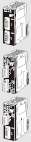 |
2 RS-232C ports | The following
functions can be selected for each port: Protocol macro Host Link NT Links (1:N mode) Serial Gateway No-protocol Modbus-RTU Slave |
1 | 0.29
*1 |
--- | CJ1W-SCU22 |
| 2 RS-422A/
485 ports |
0.46 | --- | CJ1W-SCU32 | ||||
| 1 RS-232C port
and 1 RS-422A/ 485 port |
0.38
*1 |
--- | CJ1W-SCU42 | ||||
RS-422A Converter
 |
Converts RS-232C to RS-422A/RS-485. | CJ1W-CIF11 | |||||
*1. When an NT-AL001 RS-232C/RS-422A Conversion Unit is used, this value increases by 0.15 A/Unit. Add 0.04 A/Unit when using CJ1W-CIF11 RS-422A Adapters.
EtherNet/IP Unit
| Unit
classifi- cation |
Product
name |
Specifications | No. of
unit numbers allocated |
Current
consumption (A) |
Model | |||
|---|---|---|---|---|---|---|---|---|
| Communications
cable |
Communications
functions |
Max.
Units mount- able per CPU Unit |
5 V | 24 V | ||||
| CJ1
CPU Bus Unit |
EtherNet/
IP Unit  |
Shielded
twisted-pair (STP) cable Categories: 100 Ω at 5, 5e |
Tag Data Link
Functions, Message Communications Functions, Socket Service Functions |
4 | 1 | 0.65 | --- | CJ1W-EIP21S |
EtherCAT Slave Unit
| Unit
classifi- cation |
Product
name |
Specifications | Communications
type |
No. of unit
numbers allocated |
Current
consum- ption (A) |
Model | |
|---|---|---|---|---|---|---|---|
| 5 V | 24 V | ||||||
| CJ1
CPU Bus Units |
EtherCAT
Slave Unit  |
STP (shielded
twisted-pair) cable of category 5 or higher with double shielding |
Refreshing methods:
Free-Run Mode PDO DATA SIZE: TxPDO 400byte or less/RxPDO: 400byte or less |
1 | 0.34 | --- | CJ1W-ECT21 |
DeviceNet Unit
| Unit
classifi- cation |
Product
name |
Specifications | Communications type | No. of unit
numbers allocated |
Current
consum- ption (A) |
Model | |
|---|---|---|---|---|---|---|---|
| 5 V | 24 V | ||||||
| CJ1
CPU Bus Units |
DeviceNet
Unit  |
Functions as master
and/or slave; allows control of 32,000 points max. per master. |
• Remote I/O communications
master (fixed or user-set allocations) • Remote I/O communications slave (fixed or user-set allocations) • Message communications |
1 | 0.29 | --- | CJ1W-DRM21 |
CompoNet Master Unit
| Unit
classifi- cation |
Product
name |
Specifications | No. of unit
numbers allocated |
Current
consum- ption (A) |
Model | ||
|---|---|---|---|---|---|---|---|
| Communications
functions |
No. of I/O points per
Master Unit |
5 V | 24 V | ||||
| CJ1 Special
I/O Units |
CompoNet
Master Unit  |
Remote I/O
communications Message communications |
Word Slaves: 2,048 max.
(1,024 inputs and 1,024 outputs) Bit Slaves: 512 max. (256 inputs and 256 outputs) |
1, 2, 4,
or 8 |
0.4 | --- | CJ1W-CRM21 |
Controller Link Units
| Unit
classifi- cation |
Product
name |
Specifications | No. of unit
numbers allocated |
Current
consum- ption (A) |
Model | ||||
|---|---|---|---|---|---|---|---|---|---|
| Communications
cable |
Communications
type |
Duplex
support |
Max. Units
mountable per CPU Unit |
5 V | 24 V | ||||
| CJ1
CPU Bus Unit |
Controller
Link Unit  |
Wired shielded
twisted-pair cable |
Data links and
message service |
No | 8 | 1 | 0.35 | --- | CJ1W-CLK23 |
FL-net Unit
| Unit
classifi- cation |
Product
name |
Specifications | No. of unit
numbers allocated |
Current
consumption (A) |
Model | |||
|---|---|---|---|---|---|---|---|---|
| Communications
interface |
Communications
functions |
Max. Units
mountable per CPU Units |
5 V | 24 V | ||||
| CJ1
CPU Bus Units |
FL-net
Unit  |
100Base-TX | With FL-net Ver. 2.0
specifications (OPCN-2) Data links and message service |
4 | 1 | 0.37 | --- | CJ1W-FLN22 |
SPU Unit (High-speed Data Storage Unit)
| Unit
classifi- cation |
Product
name |
Specifications | No. of unit
numbers allocated |
Current
consum- ption (A) |
Model | ||
|---|---|---|---|---|---|---|---|
| PC Card slot | Ethernet (LAN)
port |
5 V | 24 V | ||||
| CJ1
CPU Bus Units |
SPU Unit
(High- speed Data Storage Unit)  |
CF Card Type I/II ×
1 slot Use an OMRON HMC-EF[][][] Memory Card. |
1 port
(10/100Base-TX) |
1 | 0.56 | --- | CJ1W-SPU01-V2 |
Note: Use version 2 or higher of the SYSMAC SPU Unit with a CJ3 CPU Unit.
ID Sensor Units
| Unit
classification |
Product
name |
Specifications | No. of unit
numbers allocated |
Current
consumption (A) |
Model | |||
|---|---|---|---|---|---|---|---|---|
| Connected ID
Systems |
No. of
connected R/W heads |
External
power supply |
5 V | 24 V | ||||
| CJ1 CPU
Bus Units |
ID Sensor
Units  |
V680-Series
RFID System |
1 | Not
required. |
1 | 0.26 | 0.13 *1 | CJ1W-V680C11 |
| 2 | 2 | 0.32 | 0.26 | CJ1W-V680C12 | ||||
*1. To use a V680-H01 Antenna, refer to the V680 Series RFID System Catalog (Cat. No. Q151).
Peripheral Devices
Industrial Switching Hubs for EtherNet/IP and Ethernet
| Product
name |
Appearance | Functions | No. of
ports |
Accessories | Current
consumption (A) |
Model |
|---|---|---|---|---|---|---|
| Industrial
Switching Hubs |
 |
Quality of Service (QoS):
EtherNet/IP control data priority 10/100BASE-TX, Auto-Negotiation |
5 | Power supply connector | 0.07 | W4S1-05D |
Note: Industrial switching hubs cannot be used for EtherCAT.
last update: October 1, 2026
 Top of Page
© Copyright OMRON Corporation 2007 - 2026. All Rights Reserved.