Question
How do I write a program to delay turning ON a work bit for 1 scan after an input A turns ON and keep the work bit ON for only 1 scan when using a CS/CJ-series Programmable Controllers?
Answer
As shown in Figure 1, the program delays for 1 scan after input A turns ON, and turns ON work bit W2.00 for only 1 scan, as shown in Figure 2.
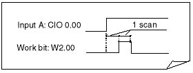
Figure 1
Ladder Programming
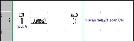
Figure 2
Operation: Refer to Figure 3
1.When input A (CIO 0.00) turns ON, the execution condition created by the differentiated input instruction (--|↑|--) will turn ON for only 1 scan.
2.When the execution condition created by the differentiated input instruction (--|↑|--) turns OFF in the next scan, the CONDITION OFF (DOWN) instruction causes the execution condition to turn ON for only one scan, resulting in work bit W2.00 turning ON for only 1 scan.
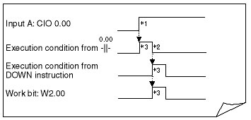
Figure 3
3.ON for 1 scan only.
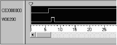
Data Trace Results
Applications of this Programming
This programming technique to delay turning ON a work bit for 1 scan after another bit’s status changes (i.e., turns ON) and then turn on the work bit for only 1 scan can be used for time limit control between a data output signal and strobe signal in parallel transmissions.
Example of Time Limit Control in Parallel Transmissions
"Transmission request input from a terminal device turns ON" to "Parallel data (n bits) is output".
to "Strobe signal (1 bit) turns ON after 1 scan".
Application Conditions for this Programming
The signal from the device must meet the following time-related conditions.
The time period required between the parallel data and strobe signal must be less than the Programmable Controllers' shortest scan time.
Recommended Products


Other Programmable Controllers FAQ
-
 What products are recommended as substitutes for the C200H-CPU01 Programmable Controller?
-
How can I connect a C200H Programmable Controller's CPU Unit with an IBM PC/AT or compatible computer?
-
Why communication error occurs during CX-Programmer FA Integrated Tool Package get online with Programmable Controller?