Question
Our Photoelectric Sensors malfunction when the power supply of an inverter motor or other equipment is switched ON or OFF. What's causing this, and what can we do to resolve it?
Answer
It's possible that the malfunction is due to electrical noise. Try a countermeasure for noise. Different countermeasures should be used depending on factors such as the path of noise entry, the frequency component, and the peak value.
Typical countermeasures for various types of noise are shown in the following table.
| Type of noise | Noise intrusion path and countermeasure | |
| Before countermeasure | After countermeasure | |
| Common mode noise (inverter noise) (Common noise applied between the mounting board and the +V and 0-V lines, respectively.) | Noise enters from the noise source through the frame (metal).  | (1) Ground the inverter motor (to 100 Ω or less) (2) Ground the noise source and the power supply (0-V side) through a capacitor (film capacitor, 0.22 µF, 630 V). (3) Insert an insulator (plastic, rubber, etc.) between the Sensor and the mounting plate (metal). 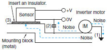 |
| Radiant noise (Ingress of high- frequency electromagnetic waves directly into Sensor, from power line, etc.) | Noise propagates through the air from the noise source and directly enters the Sensor. 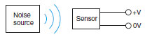 | Insert a shield (copper) plate between the Sensor and the noise source e.g., a switching power supply). Separate the noise source and the Sensor to a distance where noise does not affect operation. 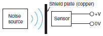 |
| Power line noise (Ingress of electromag- netic induction from high-voltage wires and switching noise from the switching power supply) | Noise enters from the power line. 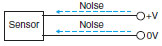 | Insert a capacitor (e.g., a film capacitor), noise filter (e.g., ferrite core or insulated transformer), or varistor in the power line. 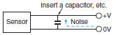 |
Recommended Products
 E2E
E2E
Standard Sensors for Detecting Ferrous Metals under Standard Conditions
Other Photoelectric Sensors FAQ
© Copyright OMRON Corporation 2007 - 2026. All Rights Reserved.