Programmable Controllers
|
|
Features |
| Principles | Classifications |
| Engineering Data |
|
| Explanation of Terms | Troubleshooting |
Related Contents
- Programmable Controllers
I/O Refresh
With the PLC, commands from user programs designed by users are executed one by one and processed by accessing data in the internal PLC memory areas (OMRON call this the "I/O Memory").
At the same time, packages of data from sensors/switches that are directly connected to the basic I/O units or PLC are exchanged with data in the PLC internal I/O Memory, at specific times. This process to totally exchange external data and internal I/O Memory data is called "I/O Refresh".
It is important to know the timing by which the I/O Refresh will be executed when considering the operation of automation systems and user programs designed by users. I/O Refresh is performed immediately following the execution of all other commands. (See figure below)

Cycle Time
In terms of the PLC processing cycle, the cycle time is the time from the execution (commencement) of the I/O refresh to the execution (processing) of the following I/O refresh.
The cycle time includes time for overhead processing (self-diagnosis), execution of user programs, I/O refreshing and peripheral servicing.
When the cycle time is long, the cycle for exchanging data with outside of the PLC and the I/O response time are also longer, making it impossible to receive an input signal that is shorter than the cycle time.
When the cycle time is short, I/O response time is also shortened, which allows high speed processing.
As the cycle time changes, the command execution cycle and I/O response times also change.
The cycle time can be calculated using the following formula:
Cycle Time = Overhead Processing Time + Total Command Execution Time + I/O Refresh Time + Peripheral Service Time
The calculation methods for each Execution Time for the PLC are included in the manuals.
Interrupt Tasks
Normally, user programs are executed in order along with the processing of the I/O refresh etc., within the PLC processing cycle (See "I/O Refresh").
Interrupt tasks however are executed in precedence to this processing cycle. In the event that certain interrupt conditions are met, the processing cycle will be suspended and the interrupt tasks will be executed first.
(The PLC sometimes refers to the "Interrupt Tasks" as "Interrupt Programs", but here we shall use "Interrupt Tasks", the terminology used in the CS/CJ Series manuals)
For example, in the case of the CS/CJ Series, interrupt tasks can include power OFF interrupts, scheduled interrupts, I/O interrupts, periodic interrupts based on the internal timer, and external interrupts.
| Major Interrupt Tasks | Details |
| Power OFF interrupt tasks | Executed when the CPU Unit power is turned OFF. |
| Scheduled interrupt tasks | Executed based on a specific schedule. |
| I/O interrupt tasks | Executed at the start-up of a connected Interrupt Input Unit. |
| External interrupt tasks | Executed when requests are received from the Special I/O Units, the CPU Bus Units, and the Inner Board (only for CS Series). |
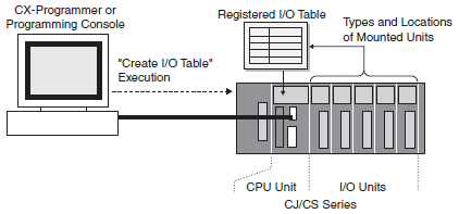
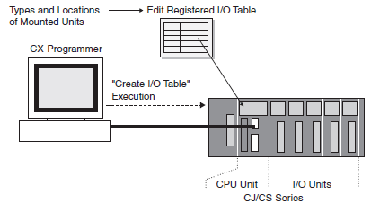
I/O Allocation
In order for user programs to utilize I/O signals from the I/O Units mounted to the PLC, it is necessary to first assign an address within the PLC I/O memory.
Allocating inputs and outputs on units mounted to the PLC in I/O memory is known as I/O Allocation. The CPU Unit uses this I/O Allocation information for I/O refresh with connected units.
This I/O Allocation information is recorded in the PLC as the "Registered I/O Table". The registered I/O Table can be created by either of two automatic registration methods: registering information of units mounted to the PLC online by executing the command from the programming tool, or transferring the I/O Table that was created offline using programming software. (Some models may not require the creation of a registered I/O Table, and others may not support the offline design of I/O tables.)
Online Automatic Registration
Offline Automatic Registration
CPU Unit Memory Area
The PLC utilizes a variety of different data including user programs, I/O memory data, comments, CPU Unit and Special I/O Unit parameters, and registered I/O table information etc.
All of this data that is used by the PLC is stored in the memory areas within the CPU Unit.
The PLC has the following types of memory areas which are backed up by a battery.
In the case of the CS/CJ Series, the contents of the memory areas are backed up using flash memory, which means that even if battery voltage is low, any user programs and parameter area data will not be lost.
User Program Area
This records user programs designed by users.
I/O Memory Areas
These areas can be accessed by command operands. I/O memory consists of CIO Area, Work Area, Holding Area, DM Area, EM Area, Timer Area that contains the Timer Completion Flags and the Timer Present Values, Counter Area that contains the Counter Completion Flags and the Counter Present Values, Task Flags, Index Registers, Data Registers, Auxiliary Area, Condition Flags, Clock Pulses, and other areas. When the PLC is turned ON, data in some areas will be retained but others will be cleared. (In some areas you can select whether to clear or retain.)
Parameter Area
This contains all of the information regarding initial settings used by the PLC.
It records information such as the PLC Setup, registered I/O tables, routing tables, and CPU Bus Unit settings.