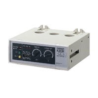
Other features, such as 100% overcurrent capacity and flush mounting are also available.
K2CM
Motor Protective Relay

Solid-state Relay Enables Choice of Three Operating Functions (Overcurrent, Openphase,and Reverse-phase)
- Features
- Lineup
- Specifications
- Dimensions
- Catalog
last update: September 24, 2012
Ratings
| Supply voltage of motor circuit | 200/220, 400/440 VAC, 50/60 Hz |
|---|---|
| Supply voltage of control circuit | 100/110/120, 200/220/240, 400/440 VAC, 50/60 Hz |
|
Insulation breakdown of output contact |
500 VAC |
|
Operating voltage/current of output contact (pf = 0.4 when breaking contact) |
NO contact: 120 VAC/2 A, 240 VAC/1 A, 440 VAC/0.5 A, 110 VDC/0.2 A, 220 VDC/0.1 A NC contact: 120 VAC/5 A, 240 VAC/2 A, 440 VAC/1 A, 110 VDC/0.2 A, 220 VDC/0.1 A |
| Contact form of output contact | Current reverse-phase detection models: SPST-NO + SPST-NC Voltage reverse-phase detection models: SPDT |
|
Operating current range of input circuit |
2 to 160 A (Number of passes: 1) |
|
Operating voltage range of control circuit |
85% to 110% of rated voltage, but operates normally at 50% of open-phase supply voltage |
|
Operating frequency range of control circuit |
95% to 105% of rated frequency |
| Power consumption | Approx. 3 VA (in standby state); 5 VA (in operating state) |
| Overcurrent function operating value | 115 ±10% of the setting value |
|
Overcurrent function operating time setting range |
Inverse Type Inverse time both at startup and during operation: Timer scale × 1 (s) at 600% overload Timer scale × 3 (s) at 200% overload Note: The above values are for a time factor setting of 1. Instantaneous Type Fixed time at starting (start-up lock) Time setting value (varies between 2 and 40 s) at 140% overload and starting Instantaneous during operation: 0.5 s max. (when current is increased from 100 to 140% of the set current value) |
| Case color | Munsell 5Y7/1 |
|
Overcurrent function operating time characteristics |
Inverse type: ±10% of maximum setting value (at 600% overload) Instantaneous type: ±20% of maximum setting value (at 140% overcurrent and at starting) |
| Overcurrent function resetting value | 100% min. of the setting value |
|
Overcurrent function start-up operating value |
Inverse type: Not applicable Instantaneous type: 30% max. of the setting value (See note.) |
| Open-phase operating value | 85% max. of the set current value (at open-phase) |
| Open-phase operating time | 2 s max. (at overcurrent operating value) |
| Reverse-phase operating value | 50% max. of the current value (80% max. of the operating voltage) |
| Reverse-phase operating time | 1 s max. (at overcurrent operating value) |
| Imbalance operating value | 85% of the set current value |
| Current imbalance factor | High: 35 ±10%; Low: 60% min. (at overcurrent operating value)  |
Note: The start-up lock timer restarts when the operating value at starting becomes less than 30% of the set current value.
Characteristics
|
Variation due to temperature fluctuation |
At 20 ±20 °C | Overcurrent: ±5% of operating value, ±10% of operating time Open-phase: ±10% of operating value, ±10% of operating time Reverse-phase: ±10% of operating value, ±10% of operating time |
|---|---|---|
| At 20 ±30 °C | Overcurrent: ±10% of operating value, ±20% of operating time Open-phase: ±20% of operating value, ±20% of operating time Reverse-phase: ±20% of operating value, ±20% of operating time |
|
| Variation due to voltage fluctuation |
At 85% to 110% of rated voltage |
Overcurrent: ±5% of operating value, ±10% of operating time Open-phase: ±5% of operating value, ±10% of operating time Reverse-phase: ±5% of operating value, ±10% of operating time |
| Variation due to frequency fluctuation |
At 95% to 105% of rated frequency |
|
| Insulation resistance | 10 MΩ min. (between current-carrying terminals and mounting panel) 5 MΩ min. (between current-carrying terminals and between contact poles) |
|
| Dielectric strength | 2,500 VAC (between current-carrying terminals and mounting panel and between current-carrying terminals) 1,000 VAC (between contact poles) |
|
| Permissible impulse voltage | Current reverse-phase detection models: 6,000 V (between current-carrying terminals and mounting panel) 4,500 V (between current-carrying terminals and between control power supply terminals) Waveform: 1.2/50 μs Voltage reverse-phase detection models: 4,500 V (between current-carrying terminals and mounting panel) Waveform: 1.2/50 μs |
|
|
Overcurrent strength of main circuit |
No abnormality develops when 20 times the set current value is applied for 2 s, 2 times with a 1minute interval. | |
|
Overvoltage strength of control power supply circuit |
No abnormality develops when 1.15 times the relay's rated voltage is applied once for 3 hours. | |
|
Variation due to waveform distortion |
No malfunction occurs when pulse containing 100% of the 2nd to 9th harmonics is applied (open phase switch set to "Low"). (See note.) | |
| Vibration | Malfunction: 10 to 55 Hz, 0.3-mm double amplitude (in X, Y, and Z directions for 10 minutes each) Destruction: 10 to 25 Hz, 2-mm double amplitude (in X, Y, and Z directions for 2 hours each) |
|
| Shock | Malfunction: 98 m/s2 (approx. 10 G) in X, Y, and Z directions Destruction: 294 m/s2 (approx. 30 G) in X, Y, and Z directions |
|
|
Test current (reference only) |
Operating time | Set time value |
| Setting characteristics of operating time | Approx. ±30% of the maximum setting value | |
| Service life | Electrical: 10,000 operations | |
| Ambient temperature | Operating: -10 to 60 °C (with no icing) Storage: -25 to 65 °C |
|
| Humidity | 35% to 85% | |
| Altitude | 2,000 m max. | |
Note: This means that no malfunction occurs with the open-phase element, but the operating value of the overload
element may vary.
element may vary.
last update: September 24, 2012