Page top

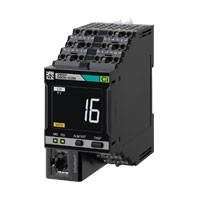
K6CM

Motor Condition Monitoring Device

K6CM

Quantifying the status of a three-phase induction motor.

Software Download

You can download software for the K6CM.

K6CM-CI

List of Models

Ratings

Power
Supply
Power supply voltage K6CM-[][]MA: 100 to 240 VAC, 50/60 Hz
K6CM-[][]MD: 24 VAC, 50/60 Hz, 24 VDC
Allowable operating voltage range 85% to 110% of power supply voltage
Power supply frequency range 45 to 65 Hz
Power consumption 24 VAC/24 VDC: 3.2 VA/1.7 W max.
100 to 240 VAC: 6.1 VA max.
Input Current,
comprehensive
current diagnosis
(CT)
Rated input
current
5 A, 25 A, 100 A, 200 A, 400 A, 600 A
Applicable motor type Three-phase induction motor (Rated voltage 600 VAC max) *1
Outputs Output form Transistor output
Output capacity 3-point
Output rating Rated voltage: 24 VDC
Max. current: 50 mA, DC
Ambient operating temperature -10 to +55°C (with no condensation or icing)
Storage temperature -20 to +65°C (with no condensation or icing)
Ambient operating humidity 25% to 85% RH (with no condensation)
Storage humidity 25% to 85% RH (with no condensation)
Case color Black
Case material Polycarbonate UL94-V0
Altitude 2,000 m max.
Applicable wires Stranded wires, solid wires, or ferrules
Applicable wire size 0.25 to 1.5 mm2 (AWG24 to 16)
Wire insertion force 8 N max. (AWG20)
Screwdriver insertion force 15 N max.
Wire stripping length 8 mm
Recommended flat-blade screwdriver XW4Z-00B (Omron)
Current capacity 10 A (per pole)
Number of insertions 50 times
Weight Approx. 200 g
Mounting Mounts to DIN Track
screw mounting
Dimensions 45 (W) × 90 (H) × 90 (D) mm
Setting method Communications settings from a dedicated tool *2 or
Condition Monitoring Configuration Tool via EtherNet/IP
Other functions Display value selection, self-diagnosis error output, setting value
initialization, operation integration
Accessories Operation manual,
CD-ROM (Motor condition monitoring Tool) *2

*1. Motors other than three-phase induction motors (synchronous motors, single phase motors, servo motors, and stepping motors) are excluded. The rated voltage of the motor applicable for UL certification is 480 VAC.
*2. The support of a dedicated tool will end in November 2024 and the CD-ROM for the Motor Condition Monitoring Tool will no longer be supplied with K6CM manufactured in December 2024 or later. Download the Condition Monitoring Configuration Tool from OMRON website and use it instead.

Characteristics

Measurement range Current
Rating 5 A: 1.00 to 5.00 A
Rating 25 A: 5.0 to 25.0 A
Rating 100 A: 20.0 to 100.0 A
Rating 200 A: 40.0 to 200.0 A
Rating 400 A: 80.0 to 400.0 A
Rating 600 A: 120.0 to 600.0 A
Rated frequency: 20 to 80 Hz

Degradation level 1, degradation level 2: 0 to 999
Recommended frequency: 20 to 80 Hz *1
Measurement
absolute
accuracy
Current ±1.0% FS±1 digit (at 10 to 30°C, CT variation is not included) *2
Sampling cycle Degradation level 1, degradation level 2, current: 5 s
Moving average frequency 1, 2, 4, 8, 16, 32 times
External
trigger
External contact input
specification
Short-circuit: Residual voltage 1.5 V max.
Open: Leakage current 0.1 mA max.
Current during short-
circuiting
Approx. 7 mA
Transistor output Contact configuration: NPN open collector
Rated voltage: 24 VDC (maximum voltage: 26.4 VDC)
Max. current: 50 mA, DC
Alarm Parameters that can be
output
Degradation level 1, degradation level 2, current
Expression method Transistor output, alarm bar
Setting value Current
Rating 5 A: 00.00 to 99.99 A
Rating 25 A/100 A/ 200 A/400 A/600 A: 0.0 to 999.9 A

Degradation level 1, degradation level 2: 0 to 9999
Hysteresis 10% width of setting value
Reset method Manual reset/automatic reset (switchable)
* Manual return method: Press the ALMRST button
LCD display 7-Segment digital display and single-shot display
Font height 14 mm
Applicable
standards
Conforming standards EN61010-2-030
Installation environment: Pollution degree 2, overvoltage category II,
measurement category II
EMC EN61326-1(EMI: Class A EMS: Industrial Location)
Current ± 10% F.S.
Safety standards UL61010-2-030 (listing) *5 / CSA 22.2 No.14 Overvoltage category II
Korean Radio Waves Act (Act 10564)
RCM
Insulation resistance 20 MΩ min.
Between all external terminals and the case
Between all power supply terminals and all other terminals
Between all sensor connection terminals and trigger input terminal +
output terminal + all EtherNet/IP ports
Dielectric strength 2,000 VAC for 1 minute
Between all external terminals and the case
Between all power supply terminals and all other terminals
Between all sensor connection terminals and trigger input terminal +
output terminal + all EtherNet/IP ports
Vibration resistance Vibration frequency 10 to 55 Hz, slice amplitude 0.35 mm in each of X, Y,
Z directions 5 minute × 10
Shock resistance 100 m/s2, 3 times each in 6 directions along 3 axes
Degree of protection IP20
LED display Alarm bar Red/Yellow/Green
MS, NS *3 Red/Green
Ethernet
communications
*4
Number of ports 1
Physical layer Ethernet: Connector RJ45
Type 100BASE-TX
Transmission distance
(Maximum cable length)
100 m (Between hub and node)
Topology Star type
Protocol EtherNet/IP
Modbus TCP

*1. When used at a frequency higher than 80 Hz, the tendency toward motor degradation is less noticeable.
*2. For the frequency characteristics of the CT, refer to the technical data on Data Sheet.
*3. MS: Product status display, NS: Network status display.
*4. A tag data link timeout may occur with products manufactured on or before April 30, 2019, over a network system including nodes set for multicast communications. Use the multicast blocking function of the switching hub to prevent multicast packets from reaching the K6CM.
*5. The rated voltage of the motor applicable for UL certification is 480 VAC.

CT

Ratings and Specifications

Model *3 K6CM-
CICB005
K6CM-
CICB025
K6CM-
CICB100
K6CM-
CICB200
K6CM-
CICB400
K6CM-
CICB600
Construction Indoor split type
Primary-side rated current 5 A 25 A 100 A 200 A 400 A 600 A
Measurement range *1 1 to 5 A 5 to 25 A 20 to 100 A 40 to 200 A 80 to 400 A 120 to 600 A
Rated voltage 600 VAC *4
Secondary-side rated current Dedicated current
Secondary winding 3000 turns 6000 turns 9000 turns
Insulation resistance Between output terminal and case: 50 MΩ min.
Dielectric strength Between output terminal and case: 2,000 VAC, 1 minute
Protective element 7.5 V clamp element
Permissible attachment/removal
frequency
100 times
Attachable wire diameter *2 7.9 mm dia.
max.
9.5 mm dia.
max.
14.5 mm dia.
max.
24.0 mm dia.
max.
35.5 mm dia. max.
Operating temperature/humidity
range
-20 to +60°C, 25 to 85% (with no condensation or icing)
Storage temperature/humidity
range
-30 to +65°C, 25 to 85% (with no condensation or icing)
Supplied cable length 2.9 m (pre-wired cable)
Supplied cable
terminal
Main unit side Ferrule terminal
CT side Round terminal
Degree of protection IP20

*1. Select a CT that brings the current of the applicable motor into the measurement range.
      To calculate the current, refer to the technical data on Data Sheet.
*2. When using a flat wire, be sure to refer to the external dimensions drawing of the CT before selection on Data Sheet.
*3. The sensor applicable for CSA certification is K6CM-CICB[][][]-C.
*4. The rated voltage of the motor applicable for UL certification is 480 VAC.

K6CM-VB

List of Models

Ratings

Power
Supply
Power supply voltage K6CM-[][]MA: 100 to 240 VAC, 50/60 Hz
K6CM-[][]MD: 24 VAC, 50/60 Hz, 24 VDC
Allowable operating voltage range 85% to 110% of power supply voltage
Power supply frequency range 45 to 65 Hz
Power consumption 24 VAC/24 VDC: 3.8 VA/2.1 W max.
100 to 240 VAC: 7.1 VA max.
Input Vibrations
(vibration sensor)
Detection
frequency
10 Hz to 10 kHz
Max. operating
acceleration
10 G
Applicable motor type Three-phase induction motor (Rated voltage 600 V or less) *1
Outputs Output form Transistor output
Output capacity 3-point
Output rating Rated voltage: 24 VDC
Max. current: 50 mA, DC
Ambient operating temperature -10 to +55°C (with no condensation or icing)
Storage temperature -20 to +65°C (with no condensation or icing)
Ambient operating humidity 25% to 85% RH (with no condensation)
Storage humidity 25% to 85% RH (with no condensation)
Case color Black
Case material Polycarbonate UL94-V0
Altitude 2,000 m max.
Applicable wires Stranded wires, solid wires, or ferrules
Applicable wire size 0.25 to 1.5 mm2 (AWG24 to 16)
Wire insertion force 8 N max. (AWG20)
Screwdriver insertion force 15 N max.
Wire stripping length 8 mm
Recommended flat-blade screwdriver XW4Z-00B (Omron)
Current capacity 10 A (per pole)
Number of insertions 50 times
Weight Approx. 200 g
Mounting Mounts to DIN Track
screw mounting
Dimensions 45 (W) × 90 (H) × 90 (D) mm
Setting method Communications settings from a dedicated tool *2 or
Condition Monitoring Configuration Tool via EtherNet/IP
Other functions Display value selection, self-diagnosis error output, setting value
initialization, operation integration
Accessories Operation manual, CD-ROM (Motor condition monitoring Tool) *2

*1. Motors other than three-phase induction motors (synchronous motors, single phase motors, servo motors, and stepping motors) are excluded.
*2. The support of a dedicated tool will end in November 2024 and the CD-ROM for the Motor Condition Monitoring Tool will no longer be supplied with K6CM manufactured in December 2024 or later. Download the Condition Monitoring Configuration Tool from OMRON website and use it instead.

Characteristics

Measurement range Acceleration: 0.05 to 9.99 G, Velocity: 0.90 to 45.00 mm/s *6,
Motor temperature: 0 to 80°C, Differential temperature: 0 to 80°C
Measurement
absolute
accuracy
Acceleration ±3 dB±2 digit (at 25°C) *5
Temperature Motor temperature: ±3°C±2 digit (±6°F±2 digit) *1
Temperature Gap: ±6°C±2 digit (±12°F±2 digit) *1
Sampling cycle Acceleration: 50 ms, Velocity: 0.5 s, Temperature: 0.5 s
Moving average frequency 1, 2, 4, 8, 16, 32 times
External
trigger
External contact input
specification
Short-circuit: Residual voltage 1.5 V max.
Open: Leakage current 0.1 mA max.
Current during short-
circuiting
Approx. 7 mA
Transistor output Contact configuration: NPN open collector
Rated voltage: 24 VDC (maximum voltage: 26.4 VDC)
Max. current: 50 mA, DC
Alarm Parameters that can
be output
Degradation level, current
Expression method Transistor output, alarm bar
Setting value Acceleration: 0.00 to 99.99 G, Velocity: 0.00 to 99.99 mm/s,
Motor temperature: 0 to 9999 deg., Differential temperature: 0 to 9999 deg.
Hysteresis 10% width of setting value
Reset method Manual reset/automatic reset (switchable)
* Manual return method: Press the ALMRST button
LCD display 7-Segment digital display and single-shot display
Font height 14 mm
Applicable
standards
Conforming standards EN61010-2-030
Installation environment: Pollution degree 2, overvoltage category II,
measurement category II
EMC EN61326-1(EMI: Class A EMS: Industrial Location)
Acceleration ± 0.1G, Velocity ±2.25mm/s, Temperature ± 6°C
Safety standards UL61010-2-030 (listing)
Korean Radio Waves Act (Act 10564)
RCM
Insulation resistance 20 MΩ min.
Between all external terminals and the case
Between all power supply terminals and all other terminals
Between all sensor connection terminals and trigger input terminal +
output terminal + all EtherNet/IP ports
Dielectric strength 2,000 VAC for 1 minute
Between all external terminals and the case
Between all power supply terminals and all other terminals
Between all sensor connection terminals and trigger input terminal +
output terminal + all EtherNet/IP ports
Vibration resistance Vibration frequency 10 to 55 Hz, slice amplitude 0.35 mm in each of X, Y,
Z directions 5 minute × 10
Shock resistance 100 m/s2, 3 times each in 6 directions along 3 axes
Degree of protection IP20
LED display Alarm bar Red/Yellow/Green
MS, NS *2 Red/Green
Ethernet
communications
*3
Number of ports 1
Physical layer Ethernet: Connector RJ45
Type 100BASE-TX
Transmission distance
(Maximum cable length)
100 m (Between hub and node)
Topology Star type
Protocol EtherNet/IP
Modbus TCP *4

*1. Except when an adhesive attachment or magnet mounting attachment is used.
*2.MS: Product status display, NS: Network status display.
*3. A tag data link timeout may occur with products manufactured on or before April 30, 2019, over a network system
     including nodes set for multicast communications. Use the multicast blocking function of the switching hub to prevent
     multicast packets from reaching the K6CM.
*4. Can be used only with EIP CPU version 1.2 or higher.
*5. Except when a magnet mounting attachment is used.
*6. Even if the motor is not moving, the value of velocity may appear slightly, so that the measurement value is fixed
     at 0.00 mm/s until the value reaches 0.90 mm/s or higher. Also, depending on the customer’s operating environment,
     the K6CM may display a measured value of 0.90 mm/s or higher even when the motor is not moving.

Input part

Vibration & temperature sensor

Ratings

Model K6CM-VBS1
Power supply voltage Supplied from K6CM-VB
Sensor head Max. acceleration 10 G
Ambient operating temperature Pre-amplifier: -10 to +55°C (with no condensation or icing)
Sensor head: -10 to +80°C (with no condensation or icing)
Storage temperature Pre-amplifier: -20 to +65°C (with no condensation or icing)
Sensor head: -20 to +90°C (with no condensation or icing)
Ambient operating humidity 25% to 85% RH (with no condensation)
Storage humidity 25% to 85% RH (with no condensation)
Altitude 2,000 m max.
Case color Pre-amplifier: Black
Sensor head: Silver
Case material Pre-amplifier: Polycarbonate UL94-V0
Sensor head: Aluminum alloy (ADC12) / Zinc die casting (ZDC2) (the threaded part
is Steel (S45C))
Weight Pre-amplifier: Approx. 210 g (including cables)
Sensor head: Approx. 40 g (including cables)
Mounting Pre-amplifier: DIN rail mounting, screw mounting
Sensor head: Screw mounting
Between pre-amplifier and sensor head: Connector connection (smart click
connector)
Wire length Between pre-amplifier and sensor head: 2.6 m+0.3 m (cannot be extended)
Between pre-amplifier and main unit: 1 m Can be extended up to a maximum length
of 100 m *

* When extending the cable on the pre-amplifier side, use shielded twisted pair cable with wire gauges of AWG24 to 16.

Characteristics

Model K6CM-VBS1
Measurement range Specified in main unit “Characteristics”
Applicable
standards
Conforming
standards
EN 61010-2-030
Installation environment: Pollution degree 2, overvoltage category II, measurement
category II
EMC EN 61326-1 (EMI: Class A EMS: Industrial Location)
Safety standards UL 61010-2-030 (listing) *
RCM
Insulation resistance 20 MΩ min.
Dielectric strength 500 VAC for one minute
Vibration
resistance
Pre-amplifier Vibration frequency 10 to 55 Hz, slice amplitude 0.35 mm in each of X, Y, Z directions
5 minute × 10
Sensor head Vibration frequency 10 to 55 Hz, slice amplitude 0.35 mm in each of X, Y, Z directions
5 minute × 10
Shock
resistance
Pre-amplifier 100 m/s2, 3 times each in 6 directions along 3 axes
Sensor head 100 m/s2, 3 times each in 6 directions along 3 axes
Degree of
protection
Pre-amplifier IP20 (excluding the sensor-side cable)
Sensor head Conforming to IP67G (JIS C 0920: 2003, Appendix 1)
LED display Pre-amplifier PWR: Green, ERR: Red, COM: Orange

* Except when K6CM-VBSAT1 or K6CM-VBSAT2 is used.

K6CM-IS

List of Models

Ratings

Power
Supply
Power supply voltage K6CM-[][]MA: 100 to 240 VAC, 50/60 Hz
K6CM-[][]MD: 24 VAC, 50/60 Hz, 24 VDC
Allowable operating voltage range 85% to 110% of power supply voltage
Power supply frequency range 45 to 65 Hz
Power consumption 24 VAC/24 VDC: 3.7 VA/2.0 W max.
100 to 240 VAC: 6.2 VA max.
Input Insulation
resistance
(ZCT (IRT))
Rated input
voltage
(Line voltage) 200 to 480 VAC, 50 Hz/60 Hz
Rated path
current
300 AAC
Applicable motor type Three-phase induction motor (Rated voltage 480 V or less) *1
Outputs Output form Transistor output
Output capacity 3-point
Output rating Rated voltage: 24 VDC
Max. current: 50 mA, DC
Ambient operating temperature -10 to +55°C (with no condensation or icing)
Storage temperature -20 to +65°C (with no condensation or icing)
Ambient operating humidity 25% to 85% RH (with no condensation)
Storage humidity 25% to 85% RH (with no condensation)
Case color Black
Case material Polycarbonate UL94-V0
Altitude 2,000 m max.
Applicable wires Stranded wires, solid wires, or ferrules
Applicable wire size 0.25 to 1.5 mm2 (AWG24 to 16)
Wire insertion force 8 N max. (AWG20)
Screwdriver insertion force 15 N max.
Wire stripping length 8 mm
Recommended flat-blade screwdriver XW4Z-00B (Omron)
Current capacity 10 A (per pole)
Number of insertions 50 times
Weight Approx. 200 g
Mounting Mounts to DIN Track
screw mounting
Dimensions 45 (W) × 90 (H) × 90 (D) mm
Setting method Communications settings from a dedicated tool *2 or
Condition Monitoring Configuration Tool via EtherNet/IP
Other functions Display value selection, self-diagnosis error output, setting value
initialization, operation integration
Accessories Operation manual, CD-ROM (Motor condition monitoring Tool) *2

*1. Motors other than three-phase induction motors (synchronous motors, single phase motors, servo motors, and stepping motors) are excluded.
*2. The support of a dedicated tool will end in November 2024 and the CD-ROM for the Motor Condition Monitoring Tool will no longer be supplied with K6CM manufactured in December 2024 or later. Download the Condition Monitoring Configuration Tool from OMRON website and use it instead.

Characteristics

Measurement range Insulation resistance: 0.000 M to 1.000 MΩ,
Leakage current: 0.0 mA to 200.0 mA
Measurement
absolute
accuracy
Insulation
resistance
±35% rdg±2 digit (when the insulation resistance is 0.2 MΩ max.), when
a 200-V/7.5-kW max. motor is used *1
±35% rdg±2 digit (when the insulation resistance is 0.4 MΩ max.), when
a 400-V/7.5-kW max. motor is used *1
Sampling cycle Normal mode: 10 s, Inverter special measurement mode: 60 s
Moving average frequency 1, 2, 4, 8, 16, 32 times
External
trigger
*2
External contact input
specification
Short-circuit: Residual voltage 1.5 V max.
Open: Leakage current 0.1 mA max.
Current during short-
circuiting
Approx. 7 mA
Transistor output Contact configuration: NPN open collector
Rated voltage: 24 VDC (maximum voltage: 26.4 VDC)
Max. current: 50 mA, DC
Alarm Parameters that can
be output
Degradation level, current
Expression method Transistor output, alarm bar
Setting value Insulation resistance: 0.000 M to 9.999 MΩ
Hysteresis 10% width of setting value
Reset method Manual reset/automatic reset (switchable)
* Manual return method: Press the ALMRST button
LCD display 7-Segment digital display and single-shot display
Font height 14 mm
Applicable
standards
Conforming standards EN61010-2-030
Installation environment: Pollution degree 2, overvoltage category II,
measurement category II
EMC EN61326-1(EMI: Class A EMS: Industrial Location)
Acceleration ± 0.1G, Velocity ±2.25mm/s, Temperature ± 6°C,
insulation resistance ± 35% rdg
Safety standards UL61010-2-030 (listing)
Korean Radio Waves Act (Act 10564)
RCM
Insulation resistance 20 MΩ min.
Between all external terminals and the case
Between all power supply terminals and all other terminals
Between all sensor connection terminals and trigger input terminal +
output terminal + all EtherNet/IP ports
Dielectric strength 2,000 VAC for 1 minute
Between all external terminals and the case
Between all power supply terminals and all other terminals
Between all sensor connection terminals and trigger input terminal +
output terminal + all EtherNet/IP ports
Vibration resistance Vibration frequency 10 to 55 Hz, slice amplitude 0.35 mm in each of X, Y,
Z directions 5 minute × 10
Shock resistance 100 m/s2, 3 times each in 6 directions along 3 axes
Degree of protection IP20
LED display Alarm bar Red/Yellow/Green
MS, NS *3 Red/Green
Ethernet
communications
*4
Number of ports 1
Physical layer Ethernet: Connector RJ45
Type 100BASE-TX
Transmission distance
(Maximum cable length)
100 m (Between hub and node)
Topology Star type
Protocol EtherNet/IP
Modbus TCP *5

*1. For details, refer to the technical data on Data Sheet.
*2. The external trigger function can be used only when the insulation resistance type is EIP CPU version 1.1 or higher.
*3. MS: Product status display, NS: Network status display.
*4. A tag data link timeout may occur with products manufactured on or before April 30, 2019, over a network system
     including nodes set for multicast communications. Use the multicast blocking function of the switching hub to prevent
     multicast packets from reaching the K6CM.
*5. Can be used only with EIP CPU version 1.2 or higher.

ZCT (IRT)

Ratings and Specifications

Model K6CM-ISZBI52
Construction Indoor split type
Rated path current 300 A
Through hole dia. 52 mm dia.
Rated voltage 200 to 480 VAC, 50 Hz/60 Hz three phase
Measurement range Specified in main unit “Characteristics”
Measurement accuracy Specified in main unit “Characteristics”
Voltage input terminal 3-terminal lead wire, Length: 1m (pre-wired cable)
Output terminal 4-terminal lead wire, Length: 1m (pre-wired cable) Available wire length 100 m max. *
Applicable
standards
Conforming
standards
EN 61010-2-030
Installation environment: Pollution degree 2, overvoltage category II, measurement
category II
EMC EN 61326-1 (EMI: Class A EMS: Industrial Location)
Safety standards UL 61010-2-030 (Recognition) + CSA C22.2 No. 61010-2-030
RCM
Insulation resistance Between Mounting bracket - Secondary winding: 100 MΩ min.
Dielectric strength Between Mounting bracket - Secondary winding: 2000 VAC, 1 minute
Ambient operating temperature -10 to +55°C (with no condensation or icing)
Ambient operating humidity 25 to 85% (with no condensation)
Weight Approx. 2.3 kg (including cables)
Degree of protection IP20

* When extending the cable on the pre-amplifier side, use shielded twisted pair cable with wire gauges of AWG24 to 16.

Motor condition monitoring Tool (Software included with main unit)

The support of a dedicated tool will end in November 2024 and the CD-ROM for the Motor Condition Monitoring Tool will no longer be supplied with K6CM manufactured in December 2024 or later. Download the Condition Monitoring Configuration Tool from OMRON website and use it instead.

Operating Environment

Element Specification
Supported OS Windows 7, Windows 8.1, Windows 10 (32 bit/64 bit) (Japanese/English)
.NET .NET Framework 4 and .NET Framework 3.5
CPU 1 GHz or more, 32 bit or 64 bit processor
Memory 1 GB or more, or 2 GB or more (for 64 bit)
HDD Available space of 16 GB or more, or 20 GB or more (for 64 bit)
Others Since this software is provided on a CD-ROM, a CD-ROM reading device must be available.
If data is to be collected, a LAN I/F must be available.

Functions/Specifications

(For more details, refer to the catalog of each product.)

Item Specification
Project Number of files that can be created No limit
Log file CSV data format
Monitoring cycle 5 second to 366 days
Number that can be
registered in one project
Number of motors (device groups) 10
Number of devices per motor (device group) 3 *1
Graphic display Type of graph Line graph
Display period *2 1 hour, 1 day, 1 month, 1 year

*1. One vibration and temperature type, one insulation resistance type, and one current comprehensive diagnosis type can
      be set for one motor.
*2. In the software tool version 1.2.0.0 and earlier, the graph display period can be set by selecting the tabs (1 hour, 1 day,
     3 months, 6 months, 1 year, 2 years, 5 years, 10 years, 20 years).
     In the software tool version 1.2.0.0 and later, you can move the graph in the time axis direction using the graph time axis
     movement.

Condition Monitoring Configuration Tool

Starting in February 2024, OMRON releases a software tool for configuring all models of condition monitoring devices. The unified configuration and verification environment of the software tool makes it easy to introduce condition monitoring devices. While the existing tools for condition monitoring devices will remain functional, be advised that OMRON has no plans to provide support for updates or related services. Going forward, use the Condition Monitoring Configuration Tool instead of the existing tools.

Product name Model Software Tool The last day to
download the tools
Motor Condition
Monitoring Device
K6CM *1 Motor Condition Monitoring Tool *2 30 November, 2024
Thermal Condition
Monitoring Device
K6PM-TH K6PM-TH Software Tool 30 June, 2024
Insulation Resistance
Monitoring Device
K7GE-MG K7GE-MG Logging Tool
Heater Condition
Monitoring Device
K7TM K7TM Configuration Tool
Advanced Motor Condition
Monitoring Device
K7DD K7DD Support Tool

*1. Can be used only for K6CM-CI2, K6CM-VB with EIP CPU version 1.20 or higher, and K6CM-IS with EIP CPU version 1.20 or higher.
*2. The CD-ROM for the Motor Condition Monitoring Tool will no longer be supplied with K6CM manufactured in December 2024 or later.

K6CM Specifications 39

The new Tool will be available from February 2024 onwards
Condition Monitoring Configuration Tool

Operating Environment

Supported OS Windows 10 (Version1607 or later) and 11 (Japanese or English)
64 bit
PC specifications CPU: 1 GHz or higher, 64 bit processor
Memory: 2 GB or higher
Disk reserved area capacity: 20 GB or more
Monitor resolution: 1920 × 1080
Others: LAN port (for network connection)

How to obtain the Condition Monitoring Configuration Tool

The Tool is provided by download only.
https://www.ia.omron.com/cmc_tool